µPD75216A
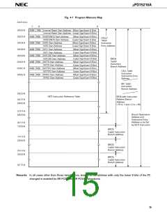
Fig. 4-1 Program Memory Map
Address
7
6
0
0000H
0002H
0004H
0006H
0008H
000AH
000CH
000EH
MBE
Internal Reset Start Address (Most Significant 6 Bits)
Internal Reset Start Address (Least Significant 8 Bits)
RBE
MBE
MBE
MBE
MBE
MBE
MBE
MBE
RBE INTBT/INT4 Start Address
(Most Significant 6 Bits)
(Least Significant 8 Bits)
(Most Significant 6 Bits)
(Least Significant 8 Bits)
(Most Significant 6 Bits)
(Least Significant 8 Bits)
(Most Significant 6 Bits)
(Least Significant 8 Bits)
(Most Significant 6 Bits)
(Least Significant 8 Bits)
(Most Significant 6 Bits)
(Least Significant 8 Bits)
(Most Significant 6 Bits)
(Least Significant 8 Bits)
CALLF
!faddr
Instruction
Entry Address
INTBT/INT4 Start Address
INT0 Start Address
RBE
RBE
INT0 Start Address
INT1 Start Address
INT1 Start Address
RBE INTCSI0 Start Address
INTCSI0 Start Address
BRCB
!caddr
Instruction
Branch Address
INTT0 Start Address
INTT0 Start Address
INTTPG Start Address
INTTPG Start Address
INTKS Start Address
INTKS Start Address
RBE
RBE
RBE
CALL !addr
Instruction
Subroutine Entry
Address
BR !addr
Instruction
Branch Address
0020H
GETI Instruction Reference Table
BR $ addr Instruction
Relative Branch
007FH
0080H
Address
(-15 to -1 and +2 to +16)
07FFH
0800H
Branch Destination
Address and
Subroutine Entry
Address to be Set
by GETI Instruction
0FFFH
1000H
BRCB
!caddr Instruction
Branch Address
1FFFH
2000H
BRCB
!caddr Instruction
Branch Address
2FFFH
3000H
BRCB
!caddr Instruction
Branch Address
3F7FH
Remarks In all cases other than those listed above, branch to the address with only the lower 8 bits of the PC
changed is enabled by BR PCDE and BR PCXA instructions.
15

 NEC [ NEC ]