CHAPTER 1 INTRODUCTION
(o) Real-time output function
This function transfers 6-bit data set beforehand to output latches upon occurrence of a timer compare
register match signal.
A 1-channel 6-bit data real-time output function is provided on chip.
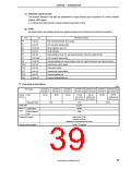
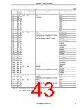
(p) Ports
As shown below, the following ports have general-purpose port functions and control pin functions.
Port
I/O
7-bit I/O
Alternate Function
P0
P1
P3
P4
P5
P7
P9
NMI, external interrupt, timer output
D/A converter analog output
Serial interface, timer I/O
Serial interface
2-bit I/O
10-bit I/O
3-bit I/O
6-bit I/O
8-bit input
16-bit I/O
4-bit I/O
2-bit I/O
4-bit I/O
6-bit I/O
16-bit I/O
Serial interface, timer I/O, key interrupt function, real-time output function
A/D converter analog input
External address bus, serial interface, timer I/O, external interrupt, key interrupt function
External bus control signal
PCM
PCS
PCT
PDH
PDL
Chip select output
External bus control signal
External address bus
External address/data bus
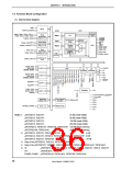
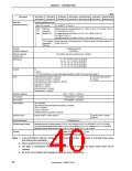
1.7 Overview of Functions
(1/2)
Part Number
ROM
µPD703212/
µPD703212Y
µPD703213/
µPD703213Y
µPD703214/
µPD70F3214/ µPD70F3214H/ µPD703215/ µPD70F3215H/
µPD703214Y µPD70F3214Y µPD70F3214HY µPD703215Y µPD70F3215HY
256 KB
Internal
memory
64 KB
96 KB
128 KB
128 KB
128 KB
256 KB
(single-power
flash memory)
(two-power
(single-power
flash memory) flash memory)
High-speed RAM
Buffer RAM
4 KB
6 KB
64 bytes
64 MB
3 MB
16 KB
Memory Logical space
space
External memory
area
External bus interface
Address bus: 22 bits
Data bus: 8/16 bits
Multiplex bus mode/separate bus mode
General-purpose registers
32 bits × 32 registers
39
User’s Manual U16890EJ1V0UD

 NEC [ NEC ]