µPD703100A-33, 703100A-40, 703101A-33, 703102A-33
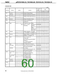
15. INSTRUCTION SET
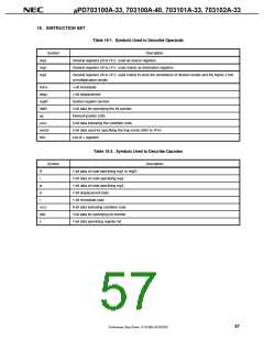
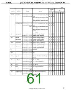
Table 15-1. Symbols Used to Describe Operands
Symbol
Description
General registers (r0 to r31): used as source registers
General registers (r0 to r31): used mainly as destination registers
reg1
reg2
reg3
General registers (r0 to r31): used mainly to store the remainders of division results and the higher 3 bits
of multiplication results
imm×
disp×
regID
bit#3
ep
×-bit immediate
×-bit displacement
System register number
3-bit data for specifying the bit number
Element pointer (r30)
cccc
vector
list×
4-bit data indicating the condition code
5-bit data used for specifying the trap vector (00H to 1FH)
List of × registers
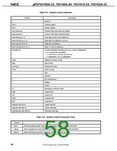
Table 15-2. Symbols Used to Describe Opcodes
Symbol
Description
1-bit data of code specifying reg1 or regID
1-bit data of code specifying reg2
1-bit data of code specifying reg3
1-bit displacement data
R
r
w
d
i
1-bit immediate data
cccc
bbb
L
4-bit data indicating condition code
3-bit data for specifying bit number
1-bit data specifying register list
57
Preliminary Data Sheet U14168EJ2V0DS00

 NEC [ NEC ]