µPD703100A-33, 703100A-40, 703101A-33, 703102A-33
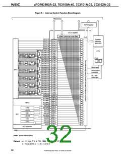
Figure 8-1. Interrupt Control Function Block Diagram
Internal bus
ISPR register
xxICn register
xxMKn (interrupt mask flag)
INTOV10
INTOV11
INTOV12
Handler
address
generator
OVIF10
OVIF11
OVIF12
INTOV13
OVIF13
INTOV14
OVIF14
INTOV15
OVIF15
INTP100/INTCC100
CPU
P10IF0
P10IF1
P10IF2
P10IF3
P11IF0
P11IF1
P11IF2
P11IF3
P12IF0
P12IF1
P12IF2
P12IF3
P13IF0
P13IF1
P13IF2
P13IF3
P14IF0
P14IF1
P14IF2
P14IF3
P15IF0
P15IF1
P15IF2
P15IF3
CMIF40
CMIF41
DMAIF0
DMAIF1
DMAIF2
DMAIF3
CSIF0
INTP101/INTCC101
INTP102/INTCC102
INTP103/INTCC103
INTP110/INTCC110
INTP111/INTCC111
INTP112/INTCC112
INTP113/INTCC113
INTP120/INTCC120
INTP100
INTP101
INTP102
INTP103
INTM1
(edge detection)
Note
Note
Note
Note
Note
Note
PSW
ID
INTP110
INTP111
INTP112
INTP113
INTM2
(edge detection)
INTP121/INTCC121
INTP122/INTCC122
Interrupt request
INTP120
INTP121
INTP122
INTP123
RPU
INTM3
(edge detection)
Interrupt request
acknowledge
INTP123/INTCC123
INTP130/INTCC130
INTP131/INTCC131
INTP132/INTCC132
INTP133/INTCC133
INTP140/INTCC140
INTP141/INTCC141
INTP142/INTCC142
INTP143/INTCC143
HALT mode
release signal
INTP130
INTP131
INTP132
INTP133
INTM4
(edge detection)
INTP140
INTP141
INTP142
INTP143
INTM5
(edge detection)
INTP150/INTCC150
INTP151/INTCC151
INTP152/INTCC152
INTP150
INTP151
INTP152
INTP153
INTM6
(edge detection)
INTP153/INTCC153
INTCM40
INTCM41
INTDMA0
INTDMA1
INTDMA2
INTDMA3
INTCSI0
INTSER0
INTSR0
DMAC
CSI0
SEIF0
SRIF0
STIF0
CSIF1
SEIF1
SRIF1
UART0
CSI1
INTST0
INTCSI1
INTSER1
INTSR1
INTST1
SIO
UART1
CSI2
STIF1
CSIF2
CSIF3
ADIF
INTCSI2
INTCSI3
INTAD
CSI3
A/D converter
NMI
Note Noise elimination
Remark xx: OV, CM, P10 to P15, DMA, CS, SE, SR, ST, AD
n: None, or 10 to 15, 40, 41, 0 to 3
32
Preliminary Data Sheet U14168EJ2V0DS00

 NEC [ NEC ]