µPD178023, 178024
2. MEMORY SPACE
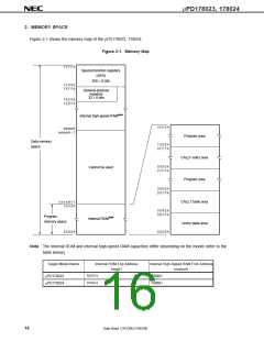
Figure 2-1 shows the memory map of the µPD178023, 178024.
Figure 2-1. Memory Map
F F F F H
Special function registers
(SFR)
256 × 8 bits
F F 0 0 H
F E F F H
General-purpose
registers
32 × 8 bits
F E E 0 H
F E D F H
Internal high-speed RAMNote
n n n n H
mmm m H
mm mm H
− 1
Program area
Data memory
space
1 0 0 0 H
0 F F F H
CALLF entry area
0 8 0 0 H
0 7 F F H
Cannot be used
Program area
0 0 8 0 H
0 0 7 F H
CALLT table area
Vector table area
n n n n H
+ 1
n n n n H
0 0 4 0 H
0 0 3 F H
Program
memory space
Internal ROMNote
0 0 0 0 H
0 0 0 0 H
Note The internal ROM and internal high-speed RAM capacities differ depending on the model (refer to the
table below).
Target Model Name
Internal ROM End Address
nnnnH
Internal High-Speed RAM First Address
mmmmH
µPD178023
µPD178024
5FFFH
7FFFH
FB00H
FB00H
16
Data Sheet U14126EJ1V0DS00

 NEC [ NEC ]