CHAPTER 12 SERIAL INTERFACE 20
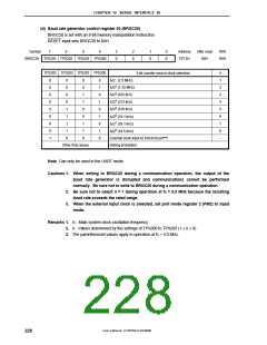
(d) Baud rate generator control register 20 (BRGC20)
BRGC20 is set with an 8-bit memory manipulation instruction.
RESET input sets BRGC20 to 00H.
Symbol
7
6
5
4
3
0
2
0
1
0
0
0
Address
FF73H
After reset
00H
R/W
R/W
BRGC20 TPS203 TPS202 TPS201 TPS200
n
TPS203 TPS202 TPS201 TPS200
3-bit counter source clock selection
0
0
0
0
0
0
0
0
1
0
0
0
0
1
1
1
1
0
0
0
1
1
0
0
1
1
0
0
1
0
1
0
1
0
1
0
f
f
f
f
f
f
f
f
X
X
X
X
X
X
X
X
/2 (2.5 MHz)
/22 (1.25 MHz)
/23 (625 kHz)
/24 (313 kHz)
/25 (156 kHz)
/26 (78.1 kHz)
/27 (39.1 kHz)
/28 (19.5 kHz)
1
2
3
4
5
6
7
8
−
External clock input to ASCK20 pinNote
Setting prohibited
Other than above
Note Can only be used in the UART mode.
Cautions 1. When writing to BRGC20 during a communication operation, the output of the
baud rate generator is disrupted and communications cannot be performed
normally. Be sure not to write to BRGC20 during a communication operation.
2. Be sure not to select n = 1 during operation at fX = 5.0 MHz because the resulting
baud rate exceeds the rated range.
3. When the external input clock is selected, set port mode register 2 (PM2) to input
mode.
Remarks 1. fX: Main system clock oscillation frequency
2. n: Values determined by the settings of TPS200 to TPS203 (1 ≤ n ≤ 8)
3. The parenthesized values apply to operation at fX = 5.0 MHz.
User’s Manual U15075EJ1V0UM00
228

 NEC [ NEC ]