CHAPTER 12 SERIAL INTERFACE 20
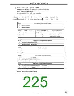
(a) Serial operation mode register 20 (CSIM20)
CSIM20 is set with a 1-bit or 8-bit memory manipulation instruction.
RESET input sets CSIM20 to 00H.
Set CSIM20 to 00H when UART mode is selected.
Symbol <7>
6
5
0
4
0
3
2
1
0
Address
FF72H
After reset
00H
R/W
R/W
CSIM20 CSIE20 SSE20
DAP20 DIR20 CSCK20 CKP20
CSIE20
3-wire serial I/O mode operation control
0
1
Operation disabled
Operation enabled
SSE20
Communication status
Function of SS20/P22 pin
Port function
SS20 pin selection
0
1
Not used
Used
Communication enabled
0
1
Communication enabled
Communication disabled
DAP20
3-wire serial I/O mode data phase selection
0
1
Outputs at the falling edge of SCK20
Outputs at the rising edge of SCK20
DIR20
First-bit specification
0
1
MSB
LSB
3-wire serial I/O mode clock selection
External clock input to the SCK20 pin
Output of the dedicated baud rate generator
CSCK20
0
1
CKP20
3-wire serial I/O mode clock phase selection
0
1
Clock is low active, and SCK20 is high level in the idle state
Clock is high active, and SCK20 is low level in the idle state
Caution Bits 4 and 5 must be set to 0.
User’s Manual U15075EJ1V0UM00
225

 NEC [ NEC ]