CHAPTER 7 8-BIT TIMER
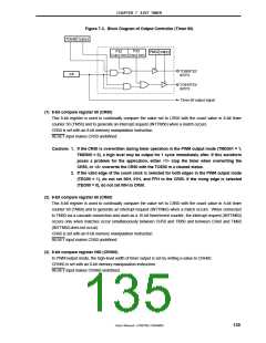
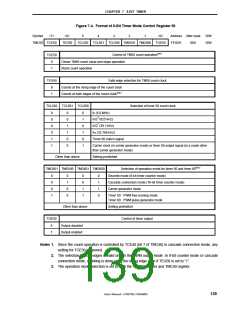
Figure 7-4. Format of 8-Bit Timer Mode Control Register 50
Symbol
<7>
<6>
5
4
3
2
1
<0>
Address After reset
FF4DH 00H
R/W
R/W
TMC50 TCE50
TEG50
TCL502 TCL501 TCL500 TMD501 TMD500 TOE50
TCE50
Control of TM50 count operationNote 1
0
1
Clears TM50 count value and stops operation
Starts count operation
TEG50
Valid edge selection for TM50 count clock
0
1
Counts at the rising edge of the count clock
Counts at both edges of the count clockNote 2
TCL502 TCL501 TCL500
Selection of timer 50 count clock
0
0
0
0
1
1
0
0
1
1
0
0
0
1
0
1
0
1
fX (5.0 MHz)
fX/23 (625 kHz)
fX/27 (39.1 kHz)
fXT (32.768 kHz)
Timer 60 match signal
Carrier clock (in carrier generator mode) or timer 60 output signal (in a mode other
than carrier generator mode)
Other than above
Setting prohibited
TMD501 TMD500 TMD601 TMD600
Selection of operation mode for timer 50 and timer 60Note 2
Discrete mode (8-bit timer counter mode)
0
0
0
1
0
1
0
0
0
0
1
1
0
1
1
0
Cascade connection mode (16-bit timer counter mode)
Carrier generator mode
Timer 50: PWM free-running mode
Timer 60: PWM pulse generator mode
Other than above
Setting prohibited
TOE50
Control of timer output
0
1
Output disabled
Output enabled
Notes 1. Since the count operation is controlled by TCE40 (bit 7 of TMC40) in cascade connection mode, any
setting for TCE30 is ignored.
2. The selection of both edges is valid only in the PWM output mode. In 8-bit counter mode or cascade
connection mode, counting is done using the rising edge even if TEG50 is set to “1”.
3. The operation mode selection is set to both the TMC30 register and TMC40 register.
User’s Manual U15075EJ1V0UM00
139

 NEC [ NEC ]