CHAPTER 7 8-BIT TIMER
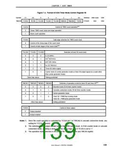
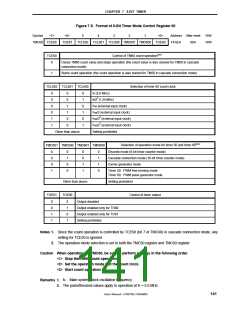
Figure 7-5. Format of 8-Bit Timer Mode Control Register 60
Symbol
<7>
<6>
5
4
3
2
1
<0>
Address After reset
FF4EH 00H
R/W
R/W
TMC60 TCE60
TOE61
TCL602 TCL601 TCL600 TMD601 TMD600 TOE60
TCE60
0
Control of TM60 count operationNote 1
Clears TM60 count value and stops operation (the count value is also cleared for TM50 in cascade
connection mode)
1
Starts count operation (the count operation is also started for TM50 in cascade connection mode)
TCL602 TCL601 TCL600
Selection of timer 60 count clock
0
0
0
0
1
1
0
0
1
1
0
0
0
1
0
1
0
1
fX (5.0 MHz)
fX/22 (1.25 MHz)
fTMI (external input clock)
fTMI/2 (external input clock)
fTMI/22 (external input clock)
fTMI/23 (external input clock)
Setting prohibited
Other than above
TMD501 TMD500 TMD601 TMD600
Selection of operation mode for timer 50 and timer 60Note 2
Discrete mode (8-bit timer counter mode)
0
0
0
1
0
1
0
0
0
0
1
1
0
1
1
0
Cascade connection mode (16-bit timer counter mode)
Carrier generator mode
Timer 50: PWM free-running mode
Timer 60: PWM pulse generator mode
Other than above
TOE60
Setting prohibited
TOE61
Control of timer output
0
0
1
1
0
1
0
1
Output disabled
Output enabled only for TO60
Output enabled only for TO61
Setting prohibited
Notes 1. Since the count operation is controlled by TCE60 (bit 7 of TMC60) in cascade connection mode, any
setting for TCE50 is ignored.
2. The operation mode selection is set to both the TMC50 register and TMC60 register.
Caution When operating the TMC60, be sure to perform settings in the following order.
<1> Stop the TM60 count operation.
<2> Set the operation mode and the count clock.
<3> Start count operation.
Remarks 1. fX: Main system clock oscillation frequency
2. The parenthesized values apply to operation at fX = 5.0 MHz.
User’s Manual U15075EJ1V0UM00
141

 NEC [ NEC ]