NTC Proprietary
Level: Property
DDR3(L)-2Gb SDRAM
NT5CB(C)256M8JQ/NT5CB(C)128M16JR
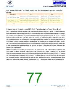
ODT timing parameters for Power Down (with DLL frozen) entry and exit transition
period
Description
Min.
Max.
min{ ODTLon * tCK + tAONmin; tAONPDmin }
min{ (WL - 2) * tCK + tAONmin; tAONPDmin }
min{ ODTLoff * tCK + tAOFmin; tAOFPDmin }
min{ (WL - 2) * tCK + tAOFmin; tAOFPDmin }
max{ ODTLon * tCK + tAONmax; tAONPDmax }
max{ (WL - 2) * tCK + tAONmax; tAONPFmax }
max{ ODTLoff * tCK + tAOFmax; tAOFPDmax }
max{ (WL - 2) * tCK + tAOFmax; tAOFPDmax }
ODT to RTT turn-on delay
ODT to RTT turn-off delay
tANPD
WL-1
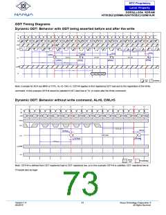
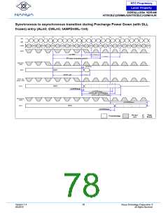
Synchronous to Asynchronous ODT Mode Transition during Power-Down Entry
If DLL is selected to be frozen in Precharge Power Down Mode by the setting of bit A12 in MR0 to “0”, there is a transition
period around power down entry, where the DDR3(L) SDRAM may show either synchronous or asynchronous ODT behavior.
The transition period is defined by the parameters tANPD and tCPDED(min). tANPD is equal to (WL-1) and is counted
backwards in time from the clock cycle where CKE is first registered low. tCPDED(min) starts with the clock cycle where
CKE is first registered low. The transition period begins with the starting point of tANPD and terminates at the end point of
tCPDED(min). If there is a Refresh command in progress while CKE goes low, then the transition period ends at the later
one of tRFC(min) after the Refresh command and the end point of tCPDED(min). Please note that the actual starting point
at tANPD is excluded from the transition period, and the actual end point at tCPDED(min) and tRFC(min, respectively, are
included in the transition period.
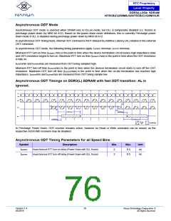
ODT assertion during the transition period may result in an RTT change as early as the smaller of tAONPDmin and
(ODTLon*tCK + tAONmin) and as late as the larger of tAONPDmax and (ODTLon*tCK + tAONmax). ODT de-assertion
during the transition period may result in an RTT change as early as the smaller of tAOFPDmin and (ODTLoff*tCK + tAOFmin)
and as late as the larger of tAOFPDmax and (ODTLoff*tCK + tAOFmax). Note that, if AL has a large value, the range where
RTT is uncertain becomes quite large. Figure 85 shows the three different cases: ODT_A, synchronous behavior before
tANPD; ODT_B has a state change during the transition period; ODT_C shows a state change after the transition period.
Version 1.4
05/2019
77
Nanya Technology Cooperation ©
All Rights Reserved.

 NANYA [ Nanya Technology Corporation. ]