• This PDF catalog is downloaded from the website of Murata Manufacturing co., ltd. Therefore, it’s specifications are subject to change or our products in it may be discontinued without advance notice. Please check with our
• Please read rating and !CAUTION (for storage, operating, rating, soldering, mounting and handling) in this catalog to prevent smoking and/or burning, etc.
!Note
!Note
C02E.pdf
sales representatives or product engineers before ordering.
• This catalog has only typical specifications because there is no space for detailed specifications. Therefore, please approve our product specifications or transact the approval sheet for product specifications before ordering0. 9.9.18
• This PDF catalog has only typical specifications because there is no space for detailed specifications. Therefore, please approve our product specifications or transact the approval sheet for product specifications before ordering.
Reference Data
Continued from the preceding page.
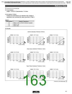
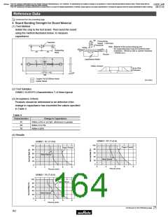
(4) Results
100
80
60
F5
40
20
0
R7
5C
360
200
240
280
320
Temperature Differential ∆T (D)
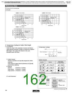
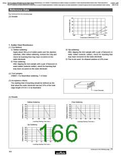
7. Solder Heat Resistance
(1) Test Method
q Reflow soldering:
e Dip soldering:
Apply about 300 µm of solder paste over the alumina
substrate. After reflow soldering, remove the chip and
check for leaching that may have occurred on the
outer electrode.
After dipping the test sample with a pair of tweezers in
static solder (eutectic solder), check for leaching that
may have occurred on the outer electrode.
r Flux to be used: An ethanol solution of 25% rosin.
8
w Flow soldering:
After dipping the test sample with a pair of tweezers in
wave solder (eutectic solder), check for leaching that
may have occurred on the outer electrode.
(2) Test samples
GRM21: For flow/reflow soldering T=0.6mm
(3) Acceptance criteria
A
The starting time of leaching should be defined as the
time when the outer electrode has lost 25% of the total
edge length of A-B-C-D as illustrated:
B
D
C
Outer Electrode
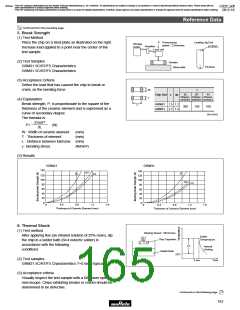
(4) Results
Reflow Soldering
Flow Soldering
280
270
260
250
240
230
220
210
280
270
260
250
240
230
220
210
0
60
120
180
240
0
10
20
30
40
50
60
Leaching Starting Time (sec.)
Leaching Starting Time (sec.)
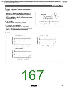
Dip Soldering
280
270
260
250
240
230
220
210
0
10
20
30
40
50
60
Leaching Starting Time (sec.)
Continued on the following page.
164

 MURATA [ muRata ]