• This PDF catalog is downloaded from the website of Murata Manufacturing co., ltd. Therefore, it’s specifications are subject to change or our products in it may be discontinued without advance notice. Please check with our
• Please read rating and !CAUTION (for storage, operating, rating, soldering, mounting and handling) in this catalog to prevent smoking and/or burning, etc.
!Note
!Note
C02E.pdf
sales representatives or product engineers before ordering.
• This catalog has only typical specifications because there is no space for detailed specifications. Therefore, please approve our product specifications or transact the approval sheet for product specifications before ordering0. 9.9.18
• This PDF catalog has only typical specifications because there is no space for detailed specifications. Therefore, please approve our product specifications or transact the approval sheet for product specifications before ordering.
Reference Data
Continued from the preceding page.
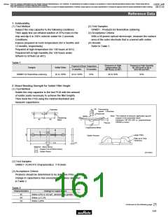
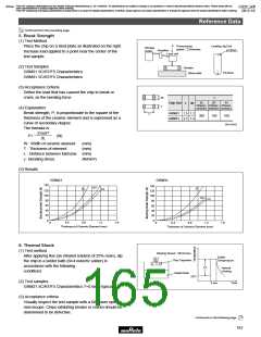
5. Break Strength
(1) Test Method
P
Pressurizing
speed : 2.5mm/sec.
Loading Jig End
φ1.0mm
Place the chip on a steel plate as illustrated on the right.
Increase load applied to a point near the center of the
test sample.
Storage
scope
Amplifier
Load cell
(2) Test Samples
Sample
Steel plate
GRM21 5C/R7/F5 Characteristics
GRM31 5C/R7/F5 Characteristics
P0.5mm
(3) Acceptance Criteria
Define the load that has caused the chip to break or
crack, as the bending force.
W
T
γ
5C
R7
F5
Chip Size
L
W
Charac- Charac- Charac-
teristics teristics teristics
(4) Explanation
Break strength, P, is proportionate to the square of the
thickness of the ceramic element and is expressed as a
curve of secondary degree.
GRM21 1.5 1.2
GRM31 2.7 1.5
L
300
180
160
(in mm)
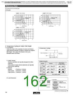
The formula is:
8
2
γ
2 WT
P=
(N)
3L
W : Width of ceramic element
T : Thickness of element
(mm)
(mm)
L : Distance between fulcrums (mm)
γ : Bending stress
(N/mm2)
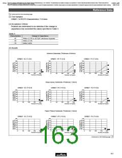
(5) Results
GRM21
GRM31
140
140
120
100
R7
5C
5C
F5
120
100
80
R7
F5
80
60
40
20
0
60
40
20
0
0
0.4
0.8
1.2
1.6
0
0.4
0.8
1.2
1.6
Thickness of Ceramic Element (mm)
Thickness of Ceramic Element (mm)
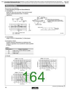
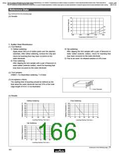
6. Thermal Shock
(1) Test method
Dipping Speed : 25mm/sec.
After applying flux (an ethanol solution of 25% rosin), dip
the chip in a solder bath (6Z4 eutectic solder) in
accordance with the following
Solder
Temperature
Chip Capacitor
∆T
Natural
Cooling
conditions:
Solder Bath
25D
(2) Test samples
2 sec.
Time
GRM21 5C/R7/F5 Characteristics T=0.6mm typical
(3) Acceptance criteria
Visually inspect the test sample with a 60-power optical
microscope. Chips exhibiting breaks or cracks should be
determined to be defective.
Continued on the following page.
163

 MURATA [ muRata ]