• This PDF catalog is downloaded from the website of Murata Manufacturing co., ltd. Therefore, it’s specifications are subject to change or our products in it may be discontinued without advance notice. Please check with our
• Please read rating and !CAUTION (for storage, operating, rating, soldering, mounting and handling) in this catalog to prevent smoking and/or burning, etc.
!Note
!Note
C02E.pdf
sales representatives or product engineers before ordering.
• This catalog has only typical specifications because there is no space for detailed specifications. Therefore, please approve our product specifications or transact the approval sheet for product specifications before ordering0. 9.9.18
• This PDF catalog has only typical specifications because there is no space for detailed specifications. Therefore, please approve our product specifications or transact the approval sheet for product specifications before ordering.
(1)
GMA Series Specifications and Test Methods(1)
In case Non "*" is added in PNs table, please refer to GMA Series Specifications and Test Methods (1).
In case "*" is added in PNs table, please refer to GMA Series Specifications and Test Methods (2).
Continued from the preceding page.
Specifications
No defects or abnormalities
R7: Within T12.5%
No.
Item
Test Method
Appearance
Capacitance
Change
Set the capacitor for 500T12 hours at 40T2D, in 90 to 95%
Humidity
humidity.
13
(Steady State)
Take it out and set it for 24T2 hours at room temperature, then
D.F.
R7: W.V.: 10V min.; 0.05 max.
measure.
More than 1,000MΩ or 50ΩF
(Whichever is smaller)
I.R.
Appearance
No defects or abnormalities
R7: Within T12.5%
Capacitance
Change
Apply the rated voltage for 500T12 hours at 40T2D, in 90 to
95% humidity and set it for 24T2 hours at room
temperature,then measure. The charge/discharge current is
less than 50mA.
Humidity
Load
14
D.F.
R7: W.V.: 10V min.; 0.05 max.
More than 500MΩ or 25ΩF
(Whichever is smaller)
I.R.
Appearance
No defects or abnormalities
R7: Within T12.5%
A voltage treatment should be given to the capacitor, in which a
DC voltage of 200% the rated voltage is applied for one hour at
the maximum operating temperature T3D then it should be set
for 24T2 hours at room temperature and the initial measurement
should be conducted.
Capacitance
Change
High
D.F.
R7: W.V.: 10V min.; 0.05 max.
15 Temperature
Load
7
Then apply the above mentioned voltage continuously for
1000T12 hours at the same temperature, remove it from the
bath, and set it for 24T2 hours at room temperature, then
measure. The charge/discharge current is less than 50mA.
More than 1,000MΩ or 50ΩF
(Whichever is smaller)
I.R.
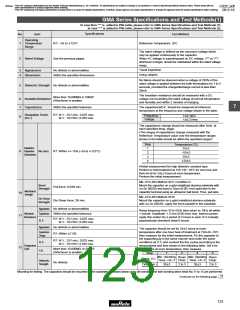
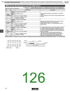
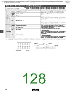
Mounting for testing: The capacitors should be mounted on the substrate as shown below using die bonding and wire bonding when tests No.11 to 15 are performed.
Capacitor
Gold wire
Die bond
Gold land
Alumina substrate
Alumina substrate
Gold land
124

 MURATA [ muRata ]