• This PDF catalog is downloaded from the website of Murata Manufacturing co., ltd. Therefore, it’s specifications are subject to change or our products in it may be discontinued without advance notice. Please check with our
• Please read rating and !CAUTION (for storage, operating, rating, soldering, mounting and handling) in this catalog to prevent smoking and/or burning, etc.
!Note
!Note
C02E.pdf
sales representatives or product engineers before ordering.
• This catalog has only typical specifications because there is no space for detailed specifications. Therefore, please approve our product specifications or transact the approval sheet for product specifications before ordering0. 9.9.18
• This PDF catalog has only typical specifications because there is no space for detailed specifications. Therefore, please approve our product specifications or transact the approval sheet for product specifications before ordering.
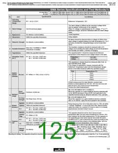
GMA Series Specifications and Test Method (1)
GMA Series Specifications and Test Methods(1)
In case Non "*" is added in PNs table, please refer to GMA Series Specifications and Test Methods (1).
In case "*" is added in PNs table, please refer to GMA Series Specifications and Test Methods (2).
Specifications
No.
1
Item
Operating
Temperature
Range
Test Method
R7: Y55 to W125D
Reference Temperature: 25D
The rated voltage is defined as the maximum voltage which
may be applied continuously to the capacitor.
P-P
O-P
2
Rated Voltage
See the previous pages.
When AC voltage is superimposed on DC voltage, V or V ,
whichever is larger, should be maintained within the rated voltage
range.
Visual inspection
Using calipers
3
4
Appearance
Dimensions
No defects or abnormalities
Within the specified dimensions
No failure should be observed when a voltage of 250% of the
rated voltage is applied between the both terminations for 1 to 5
seconds, provided the charge/discharge current is less than
50mA.
5
Dielectric Strength No defects or abnormalities
The insulation resistance should be measured with a DC
voltage not exceeding the rated voltage at normal temperature
and humidity and within 2 minutes of charging.
More than 10,000MΩ or 500ΩF
Insulation Resistance
6
7
(Whichever is smaller)
7
Capacitance
Within the specified tolerance
The capacitance/D.F. should be measured at reference
temperature at the frequency and voltage shown in the table.
Dissipation Factor
(D.F.)
R7: W.V.: 25V min.; 0.025 max.
R7: W.V.: 16V/10V; 0.035 max.
Frequency
Voltage
1T0.1kHz
1T0.2Vrms
8
The capacitance change should be measured after 5min. at
each specified temp. stage.
#The ranges of capacitance change compared with the
Reference Temperature value over the temperature ranges
shown in the table should be within the specified ranges.*
Step
Temperature (°C)
Capacitance
1
2
3
4
25T2
R7: Within W/–15% (–55 to W125°C)
9
Temperature
No bias
–55T3
25T2
Characteristics
125T3
*Initial measurement for high dielectric constant type
Perform a heat treatment at 150 W0/Y10°C for one hour and
then let sit for 24T2 hours at room temperature.
Perform the initial measurement.
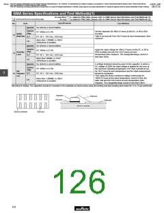
MIL-STD-883 Method 2011 Condition D
Bond
Strength
Mount the capacitor on a gold metallized alumina substrate with
Au-Sn (80/20) and bond a 25µm (0.001 inch) gold wire to the
capacitor terminal using an ultrasonic ball bond. Then, pull wire.
Pull force: 0.03N min.
Mechanical
Strength
10
11
MIL-STD-883 Method 2019
Mount the capacitor on a gold metallized alumina substrate
with Au-Sn (80/20). Apply the force parallel to the substrate.
Die Shear
Strength
Die Shear force: 2N min.
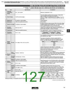
Appearance
Capacitance
No defects or abnormalities
Within the specified tolerance
Ramp frequency from 10 to 55Hz then return to 10Hz all within
1 minute. Amplitude: 1.5 mm (0.06 inch) max. total excursion.
Apply this motion for a period of 2 hours in each of 3 mutually
perpendicular directions (total 6 hours).
Vibration
Resistance
R7: W.V.: 25V min.; 0.025 max.
R7: W.V.: 16V/10V; 0.035 max.
D.F.
Appearance
No defects or abnormalities
The capacitor should be set for 24T2 hours at room
Capacitance
Change
temperature after one hour heat of treatment at 150W0/Y10D,
then measure for the initial measurement. Fix the capacitor to
the supporting jig in the same manner and under the same
conditions as (11) and conduct the five cycles according to the
temperatures and time shown in the following table. Set it for
24T2 hours at room temperature, then measure.
R7: Within T7.5%
R7: W.V.: 25V min.; 0.025 max.
R7: W.V.: 16V/10V; 0.035 max.
D.F.
I.R.
Temperature
Cycle
12
More than 10,000MΩ or 500ΩF
(Whichever is smaller)
Step
1
2
3
4
Min. Operating
Temp. W0/Y3
Max. Operating
Temp. W3/Y0
Room
Temp.
Room
Temp.
Temp. (D)
Dielectric
Strength
No defects
30T3
30T3
Time (min.)
2 to 3
2 to 3
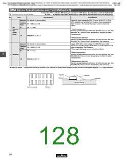
Mounting for testing: The capacitors should be mounted on the substrate as shown below using die bonding and wire bonding when tests No.11 to 15 are performed.
Continued on the following page.
123

 MURATA [ muRata ]