■AEC-Q200 Murata Standard Specification and Test Methods
No
AEC-Q200 Test Item
Specification.
AEC-Q200 Test Method
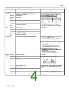
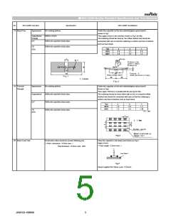
18 Board Flex
Appearance
No marking defects
Within ±10.0%
Solder the capacitor on the test substrate(glass epoxy board)
shown in Fig1.
Capacitance
Change
Then apply a force in the direction shown in Fig 2 for 60s.
The soldering should be done by the reflow method and should be
D.F.
Within the specified initial value.
Within the specified initial value.
conducted with care so that the soldering is uniform and free of defects
such as heat shock.
I.R.
Type
GCD18
GCD21
a
b
c
25℃
0.6
0.8
2.2
3.0
0.9
1.3
b
a
50 min.
f4.5
20
Pressurizing
speed:1.0mm/s
Pressurize
R4
Flexure:2
(High Dielectric Type)
100
Capacitance meter
45 45
Fig.1
t : 1.6mm
Fig.2
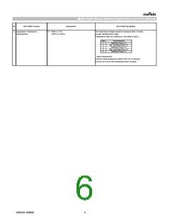
19 Terminal
Strength
Appearance
Capacitance
D.F.
No marking defects
Solder the capacitor on the test substrate(glass epoxy board)
shown in Fig3.
Then apply 18N force in parallel with the test jig for 60s.
The soldering should be done either with an iron or using the reflow
method and should be conducted with care so that the soldering is
uniform and free of defects such as heat shock
Within the specified initial value.
Within the specified initial value.
Within the specified initial value.
Type
GCD18
GCD21
a
b
c
1.0
1.2
3.0
4.0
1.2
1.65
I.R.
(in : mm)
25℃
c
t: 1.6mm
Solder resist
Baked electrode or
Copper foil
Fig.3
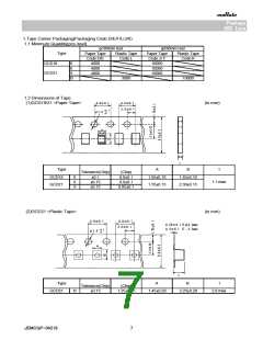
20 Beam Load Test
Destruction value should be exceed following one.
< Chip L dimension : 2.5mm max. >
Place the capacitor in the beam load fixture as Fig 4.
Apply a force.
< Chip Length : 2.5mm max. >
Chip thickness > 0.5mm rank : 20N
Iron Board
Fig.4
Speed supplied the Stress Load : 0.5mm/s
JEMCGS-00806D
5

 MURATA [ muRata ]