• Please read rating and !CAUTION (for storage, operating, rating, soldering, mounting and handling) in this catalog to prevent smoking and/or burning, etc.
• This catalog has only typical specifications because there is no space for detailed specifications. Therefore, please review our product specifications or consult the approval sheet for product specifications before ordering.
!Note
C85E.pdf
Jul.13,2011
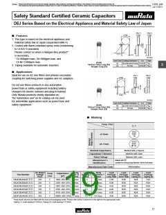
(Which Meet Japanese Law) Specifications and Test Methods
DEJ Series Specifications and Test Methods
Operating Temperature Range: -25 to +85°C
No.
Item
Specifications
Test Method
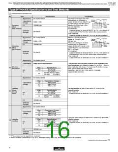
The capacitor should be visually inspected for evidence of
defect.
Dimensions should be measured with slide calipers.
No visible defect, and dimensions are within
specified range.
1
Appearance and Dimensions
2
3
Marking
To be easily legible
The capacitor should be visually inspected.
The capacitance should be measured at 20˚C with 1±0.1kHz
and AC5V(r.m.s.) max.
Capacitance
Within specified tolerance
Char.
E
F
Specifications
D.F.V2.5%
D.F.V5.0%
Dissipation Factor
(D.F.)
The dissipation factor should be measured at 20˚C with
1±0.1kHz and AC5V(r.m.s.) max.
4
5
The insulation resistance should be measured with
DC500±50V within 60±5 sec. of charging.
Insulation Resistance (I.R.)
10000MΩ min.
Between Lead
Wires
The capacitor should not be damaged when AC1500V(r.m.s.)
are applied between the lead wires for 60 sec.
No failure
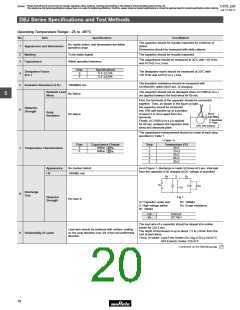
5
First, the terminals of the capacitor should be connected
together. Then, as shown in the figure at right,
the capacitor should be immersed
Dielectric
Strength
Body
6
into 10% salt solution up to a position
About
3 to 4mm
No failure
of about 3 to 4mm apart from the
terminals.
Insulation
Electrode
Plate
10% Salt Solution
Finally, AC1500V(r.m.s.) is applied
for 60 sec. between the capacitor lead
wires and electrode plate.
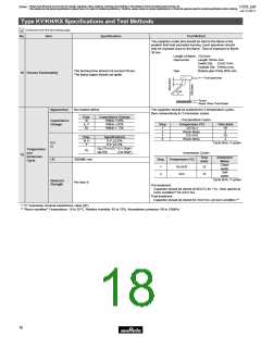
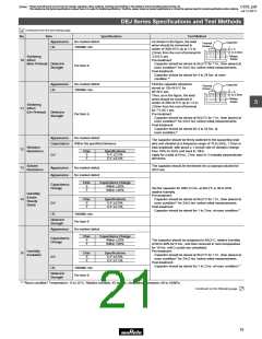
The capacitance measurement should be made at each step
specified in Table 1.
<Table 1>
Char.
E
F
Capacitance Change
Step
Temperature (ºC)
+20
–55
7
Temperature Characteristics
Within
Within
%
%
1
2
3
4
5
20±2
-25±2
20±2
85±2
20±2
+30
–80
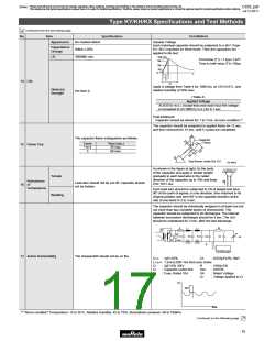
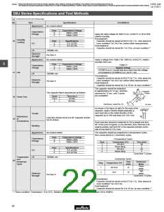
Appearance
I.R.
No marked defect
As in Figure 1, discharge is made 50 times at 5 sec. intervals
from the capacitor (Cd) charged at DC voltage of specified.
1000MΩ min.
R3
S
R1
Vs
Ct
R2
Cd
Discharge
Test
8
Dielectric
Strength
Fig.1
Per Item 6
Ct: Capacitor under test
S: High-voltage switch
R1: 1000Ω
R2: 100MΩ
R3: Surge resistance
Cd
Vs
0.001µF
DC10kV
The lead wire of a capacitor should be dipped into molten
solder for 2±0.5 sec.
The depth of immersion is up to about 1.5 to 2.0mm from the
root of lead wires.
Temp. of solder: Lead Free Solder (Sn-3Ag-0.5Cu) 245±5°C
H63 Eutectic Solder 235±5°C
Lead wire should be soldered with uniform coating
on the axial direction over 3/4 of the circumferential
direction.
9
Solderability of Leads
Continued on the following page.
18

 MURATA [ muRata ]