• Please read rating and !CAUTION (for storage, operating, rating, soldering, mounting and handling) in this catalog to prevent smoking and/or burning, etc.
• This catalog has only typical specifications because there is no space for detailed specifications. Therefore, please review our product specifications or consult the approval sheet for product specifications before ordering.
!Note
C85E.pdf
Jul.13,2011
(Which Meet Japanese Law) Specifications and Test Methods
DEJ Series Specifications and Test Methods
Continued from the preceding page.
No.
Item
Specifications
Test Method
Appearance
No marked defect
Char.
E
F
Capacitance Change
Within ±20%
Capacitance
Change
Apply the rated voltage for 500±12 hrs. at 40±2˚C in 90 to 95%
Within ±30%
relative humidity.
Pre-treatment:
Humidity
Loading
16
Char.
E
F
Specifications
D.F.V5.0%
D.F.V7.5%
Capacitor should be stored at 85±2˚C for 1 hr., then placed at
room condition*1 for 24±2 hrs. before initial measurements.
Post-treatment:
D.F.
Capacitor should be stored for 1 to 2 hrs. at room condition.*1
I.R.
1000MΩ min.
Per Item 6
Dielectric
Strength
Appearance
No marked defect
Apply a voltage from Table 2 for 1500 hrs. at 85±2˚C, relative
humidity 50% max.
5
Char.
E
F
Capacitance Change
Within ±20%
<Table 2>
Capacitance
Change
Applied Voltage
AC500V(r.m.s.), except that once each hour the voltage
is increased to AC1000V(r.m.s.) for 0.1 sec.
Within ±30%
17 Life
I.R.
1000MΩ min.
Pre-treatment:
Capacitor should be stored at 85±2˚C for 1 hr., then placed at
room condition*1 for 24±2 hrs. before initial measurements.
Post-treatment:
Dielectric
Strength
Per Item 6
Capacitor should be stored for 4 to 24 hrs. at room condition.*1
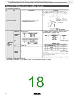
The capacitor should be subjected
to applied flame for 15 sec. and then
removed for 15 sec. until 3 cycles
are completed.
Capacitor
Flame
The capacitor flame discontinued as follows.
Cycle
1 to 2
3
Time (sec.)
15 max.
60 max.
18 Flame Test
Gas Burner: Inside Dia. 9.5
(in mm)
As shown in the figure at right, fix the body of the
capacitor, apply a tensile weight gradually to
each lead wire in the radial direction of the
capacitor up to 10N and keep it for 10±1 sec.
Tensile
W
Robustness
19 of
Lead wire should not be cut off. Capacitor should
not be broken.
Terminations
Each lead wire should be subjected to 5N of weight and bent
90° at the point of egress, in one direction, then returned to its
original position and bent 90° in the opposite direction at the
rate of one bend in 2 to 3 sec.
Bending
Appearance
No marked defect
The capacitor should be subjected to 5 temperature cycles,
then consecutively to 2 immersion cycles.
Char.
E
F
Capacitance Change
Within ±20%
Capacitance
Change
<Temperature Cycle>
Within ±30%
Step
Temperature (ºC)
-25+0/-3
Room temp.
85+3/-0
Time (min)
1
2
3
4
30
3
30
3
Char.
E
F
Specifications
D.F.V5.0%
D.F.V7.5%
D.F.
I.R.
Room temp.
Cycle time: 5 cycles
Temperature
1000MΩ min.
<Immersion Cycle>
and
Immersion
20
Time
(min)
Immersion
Water
Step
Temperature (ºC)
Cycle
Clean
water
Salt
water
1
2
65+5/-0
15
0±3
15
Dielectric
Strength
Per Item 6
Cycle time: 2 cycles
Pre-treatment:
Capacitor should be stored at 85±2˚C for 1 hr., then placed at
room condition*1 for 24±2 hrs.
Post-treatment:
Capacitor should be stored for 4 to 24 hrs. at room condition.*1
*1 "Room condition" Temperature: 15 to 35°C, Relative humidity: 45 to 75%, Atmospheric pressure: 86 to 106kPa
20

 MURATA [ muRata ]