• Please read rating and !CAUTION (for storage, operating, rating, soldering, mounting and handling) in this catalog to prevent smoking and/or burning, etc.
• This catalog has only typical specifications because there is no space for detailed specifications. Therefore, please review our product specifications or consult the approval sheet for product specifications before ordering.
!Note
C85E.pdf
Jul.13,2011
Safety Standard Certified Type KY/KH/KX Specifications and Test Methods
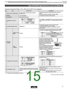
Type KY/KH/KX Specifications and Test Methods
Continued from the preceding page.
No.
Item
Appearance
Specifications
Test Method
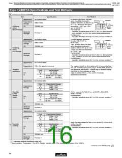
As shown in the figure, the lead
No marked defect
Within ±10%
Capacitor
1.5
Thermal
Screen
wires should be immersed in
solder of 350±10°C or 260±5°C up
to 1.5 to 2.0mm from the root of
terminal for 3.5±0.5 sec. (10±1
sec. for 260±5°C).
Capacitance
Change
to 2.0mm
Soldering
Effect
I.R.
1000MΩ min.
Molten
Solder
9
(Non-Preheat)
Pre-treatment:
Capacitor should be stored at 85±2°C for 1 hr., then placed at
room condition*2 for 24±2 hrs. before initial measurements.
Post-treatment:
Dielectric
Strength
Per Item 6
Capacitor should be stored for 1 to 2 hrs. at room condition.*2
4
Appearance
No marked defect
Within ±10%
First the capacitor should be
stored at 120+0/-5°C for
60+0/-5 sec.
Then, as in the figure, the lead
Capacitor
Thermal
Screen
Capacitance
Change
1.5
to 2.0mm
I.R.
1000MΩ min.
wires should be immersed in
Molten
Soldering
10 Effect
(On-Preheat)
solder of 260+0/-5°C up to 1.5 to
2.0mm from the root of terminal
for 7.5+0/-1 sec.
Solder
Pre-treatment:
Dielectric
Strength
Per Item 6
Capacitor should be stored at 85±2°C for 1 hr., then placed at
room condition*2 for 24±2 hrs. before initial measurements.
Post-treatment:
Capacitor should be stored for 1 to 2 hrs. at room condition.*2
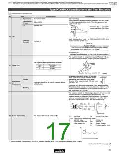
Appearance
Capacitance
No marked defect
Within the specified tolerance
The capacitor should be firmly soldered to the supporting lead
wire and vibrated at a frequency range of 10 to 55Hz, 1.5mm in
total amplitude, with about a 1-minute rate of vibration change
from 10Hz to 55Hz and back to 10Hz.
Apply for a total of 6 hrs., 2 hrs. each in 3 mutually
perpendicular directions.
Vibration
Resistance
11
Char.
B, E
F
Specifications
D.F.V2.5%
D.F.V5.0%
D.F.
Q
QU400+20C*1(CF30pF)
QU1000
SL
(CU30pF)
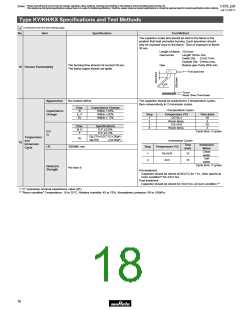
Appearance
No marked defect
Char.
B
E, F
SL
Capacitance Change
Within ±10%
Capacitance
Change
Within ±15%
Within ± 5%
Humidity
(Under
Steady
State)
Set the capacitor for 500±12 hrs. at 40±2°C in 90 to 95%
relative humidity.
Char.
B, E
F
Specifications
D.F.V5.0%
12
Post-treatment:
D.F.
Q
D.F.V7.5%
Capacitor should be stored for 1 to 2 hrs. at room condition.*2
QU275+5/2C*1(CF30pF)
SL
QU350
(CU30pF)
I.R.
3000MΩ min.
Dielectric
Strength
Per Item 6
Appearance
No marked defect
Char.
B
E, F
SL
Capacitance Change
Within ±10%
Capacitance
Change
Within ±15%
Within ± 5%
Apply the rated voltage for 500±12 hrs. at 40±2°C in 90 to 95%
relative humidity.
Humidity
Loading
Char.
B, E
F
Specifications
D.F.V5.0%
13
Post-treatment:
D.F.
Q
D.F.V7.5%
Capacitor should be stored for 1 to 2 hrs. at room condition.*2
QU275+5/2C*1(CF30pF)
SL
QU350
(CU30pF)
I.R.
3000MΩ min.
Dielectric
Strength
Per Item 6
*1 "C" expresses nominal capacitance value (pF).
*2 "Room condition" Temperature: 15 to 35°C, Relative humidity: 45 to 75%, Atmospheric pressure: 86 to 106kPa
Continued on the following page.
14

 MURATA [ muRata ]