MPQ28261 – 21V, 3A, 500kHz SYNCHRONOUS STEP-DOWN CONVERTER
Selecting the Input Capacitor
Where L1 is the inductor value and RESR is the
ESR value of the output capacitor.
The MPQ28261 requires an input capacitor (C1) to
supply the AC current to the step-down
converter while maintaining the DC input
voltage, because the input current to the step-
down converter is discontinuous. Use
capacitors with low equivalent series resistance
(ESR)—such as ceramic capacitors with X5R or
X7R dielectrics with low ESR and small
temperature coefficients. For most applications,
use a 22µF capacitor.
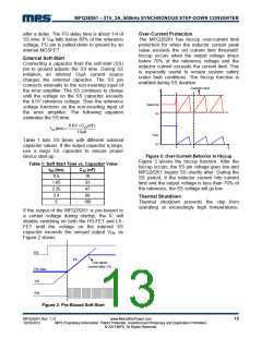
For ceramic capacitors, the capacitor
dominates the impedance at the switching
frequency, and subsequently dominates the
output voltage ripple. For simplicity, the output
voltage ripple can be estimated as:
⎛
⎞
⎟
⎠
VOUT
8× fS2 ×L1×C2
VOUT
ΔVOUT
=
× 1−
⎜
V
⎝
IN
For tantalum or electrolytic capacitors, the ESR
dominates the impedance at the switching
frequency. Subsequently, the output ripple can
be approximated as:
Since C1 absorbs the input switching current, it
must withstand significant ripple current. The
RMS current in the input capacitor can be
estimated by:
VOUT
VOUT
⎛
⎞
ΔVOUT
=
× 1−
×RESR
⎜
⎟
⎠
⎛
⎞
⎟
fS ×L1
V
IN
VOUT
VIN
VOUT
VIN
⎝
⎜
IC1 = ILOAD
×
× 1−
⎜
⎝
⎟
⎠
The characteristics of the output capacitor also
affect the system regulation stability. The
MPQ28261 can be optimized for a wide range
of capacitances and ESR values.
The worse case condition occurs at VIN = 2VOUT
where:
,
ILOAD
The maximum capacitance is 1100μF. (Tested
on Chroma 63030, CCH mode, 3A load current,
soft start capacitor is 100nF, VOUT=5V).
IC1
=
2
For simplification, choose an input capacitor
with an RMS current rating greater than half of
the maximum load current.
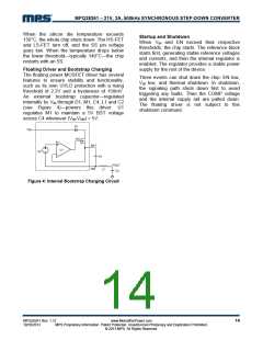
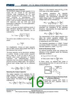
External Bootstrap Diode
An external bootstrap diode may enhance the
efficiency of the regulator under the following
applicable conditions:
The input capacitor can be electrolytic, tantalum
or ceramic. Include a small ceramic capacitor
with a value of ~0.1µF as close to the IC as
possible when using electrolytic or tantalum
capacitors. Use sufficiently-large ceramic
capacitors that can provide sufficient charge to
prevent excessive voltage ripple. The capacitor-
induced input voltage ripple can be estimated
by:
z VOUT is 5V or 3.3V; and
VOUT
z Duty cycle is high: D=
>65%
VIN
In these cases, an external BST diode is
recommended from the VCC pin to BST pin, as
shown in Figure 6.
External BST Diode
IN4148
⎛
⎞
⎟
⎠
ILOAD
VOUT
VOUT
BST
VCC
ΔV =
×
× 1−
⎜
IN
CBST
fS ×C1
V
IN
V
IN
⎝
MPQ28261
SW
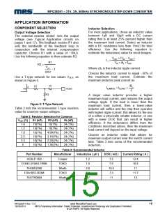
Selecting the Output Capacitor
+
COUT
L
The output capacitor (C2) maintains the DC
output voltage. Use ceramic, tantalum, or low-
ESR electrolytic capacitors to minimize the
output voltage. The output voltage ripple can be
estimated as:
Figure 6: Add Optional External Bootstrap Diode
to Enhance Efficiency
The recommended external BST diode is
IN4148 where the BST capacitor value is
between 0.1 and 1μF.
⎛
⎞
⎟
⎠
⎛
⎞
⎟
⎠
VOUT
VOUT
1
ΔVOUT
=
× 1−
× R
+
ESR
⎜
⎜
fS ×L1
V
8× fS ×C2
⎝
IN
⎝
MPQ28261 Rev. 1.12
10/10/2013
www.MonolithicPower.com
MPS Proprietary Information. Patent Protected. Unauthorized Photocopy and Duplication Prohibited.
© 2013 MPS. All Rights Reserved.
16

 MPS [ MONOLITHIC POWER SYSTEMS ]