MPQ28261 – 21V, 3A, 500kHz SYNCHRONOUS STEP-DOWN CONVERTER
APPLICATION INFORMATION
COMPONENT SELECTION
Inductor Selection
For most applications, chose an inductor value
between 1µH and 10µH with a DC current
rating that is at least 25% percent higher than
the maximum load current. Select an inductor
with a DC resistance less than 15mꢀ for best
efficiency. Use the following equation to
estimate the inductance value for most designs:
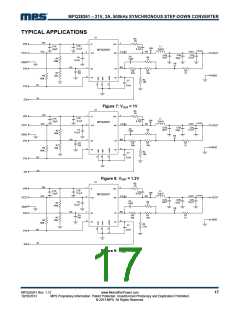
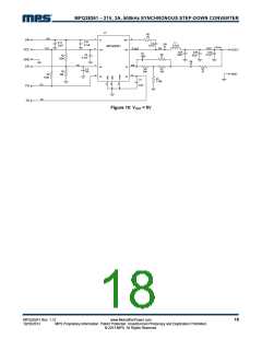
Output Voltage Selection
The external resistor divider sets the output
voltage (see Typical Application circuits on
pages 1 and 17). The feedback resistor R1 also
sets the bandwidth of the feedback loop in
conjunction with the internal compensation
capacitor. Choose R1 with a value of ~10kꢀ.
Use the following equation to then estimate R2:
VOUT ×(V − VOUT
)
IN
L1 =
R1
V × ΔIL × fOSC
IN
R2 =
V
OUT
Where ΔIL is the inductor ripple current.
− 1
0.6V
Choose the inductor current to equal ~30% of
the maximum load current. Estimate the
maximum inductor peak current as:
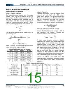
Use a T-type network for low values VOUT, as
shown in Figure 5.
ΔIL
R1
RT
8
IL(MAX) = ILOAD
+
FB
VOUT
2
R2
A larger value inductor provides a higher
maximum load current, and reduces the output
voltage ripple. If the load is lower than the
maximum load current, then a lower-value
inductor will suffice and the chip then operates
with higher ripple current; this allows for the use
of a either a physically smaller inductor, or one
with a lower DCR that can result in higher
efficiency. If the inductance differs from the
conditions described above, then the maximum
load current will depend on the input voltage.
Figure 5: T-Type Network
Table 2 lists the recommended T-type resistors
value for common output voltages.
Table 2: Resistor Selection for Common
V
OUT (V)
1.0
1.2
1.8
2.5
3.3
5
R1 (kΩ)
10(1%)
10(1%)
10(1%)
10(1%)
10(1%)
10(1%)
R2 (kΩ)
15(1%)
Rt (kΩ)
24 (1%)
24 (1%)
24 (1%)
24 (1%)
24 (1%)
24 (1%)
10(1%)
4.99(1%)
3.16(1%)
2.20(1%)
1.36(1%)
Choose an inductor value that allows for
maximum output current near the switch current
limit. Table 3 lists some of the recommended
inductors.
Table 3: Recommended Inductor
Part Number
HC8LP-1R2
Manufacturer
Inductance ( µH )
DCR ( mΩ )
Current Rating ( A )
Cooper
TOKO
Wurth
TOKO
Wurth
1.2
1.8
2.8
3.3
4.7
7.5
7.6
10.5
7.3
11
12.4
10.4
11
D104C-919AS-1R8N
7443552280
FDA1055-3R3M
7447709004
11.7
13
MPQ28261 Rev. 1.12
10/10/2013
www.MonolithicPower.com
MPS Proprietary Information. Patent Protected. Unauthorized Photocopy and Duplication Prohibited.
© 2013 MPS. All Rights Reserved.
15

 MPS [ MONOLITHIC POWER SYSTEMS ]