Freescale Semiconductor, Inc.
Multiple Serial Interface
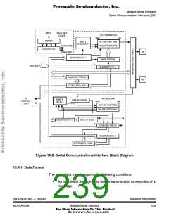
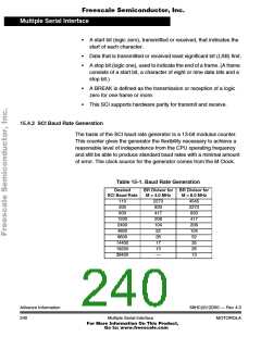
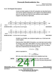
Serial Communication Interface (SCI)
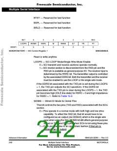
RSRC — Receiver Source
When LOOPS = 1, the RSRC bit determines the internal feedback
path for the receiver.
0 = Receiver input is connected to the transmitter internally (not
TXD pin)
1 = Receiver input is connected to the TXD pin
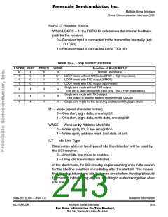
Table 15-2. Loop Mode Functions
LOOPS RSRC
DDSI(3)
WOMS
Function of Port S Bit 1/3
Normal Operations
LOOP mode without TXD output(TXD = High Impedance)
LOOP mode with TXD output (CMOS)
LOOP mode with TXD output (open-drain)
0
1
1
1
x
0
0
0
x
0
1
1
x
0/1
1
1
Single wire mode without TXD output
(the pin is used as receiver input only, TXD = High Impedance)
1
1
0
x
Single wire mode with TXD output
(the output is also fed back to receiver input, CMOS)
Single wire mode for the receiving and transmitting(open-drain)
1
1
1
1
1
1
0
1
M — Mode (select character format)
0 = One start, eight data, one stop bit
1 = One start, eight data, ninth data, one stop bit
WAKE — Wake-up by Address Mark/Idle
0 = Wake up by IDLE line recognition
1 = Wake up by address mark (last data bit set)
ILT — Idle Line Type
Determines which of two types of idle line detection will be used by
the SCI receiver.
0 = Short idle line mode is enabled.
1 = Long idle line mode is detected.
In the short mode, the SCI circuitry begins counting ones in the search
for the idle line condition immediately after the start bit. This means
that the stop bit and any bits that were ones before the stop bit could
be counted in that string of ones, resulting in earlier recognition of an
idle line.
68HC(9)12D60 — Rev 4.0
MOTOROLA
Advance Information
Multiple Serial Interface
243
For More Information On This Product,
Go to: www.freescale.com

 MOTOROLA [ MOTOROLA ]