Freescale Semiconductor, Inc.
Pulse Width Modulator
possible to know where the count is with respect to the duty value and
software can be used to make adjustments by turning the enable bit off
and on.
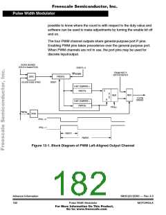
The four PWM channel outputs share general-purpose port P pins.
Enabling PWM pins takes precedence over the general-purpose port.
When PWM channels are not in use, the port pins may be used for
discrete input/output.
CLOCK SOURCE
(ECLK or Scaled ECLK)
CENTR = 0
FROM PORT P
DATA REGISTER
UP/DOWN
GATE
PWCNTx
(CLOCK EDGE SYNC)
RESET
8-BIT COMPARE =
S
PWDTYx
Q
Q
MUX
MUX
TO PIN
DRIVER
R
8-BIT COMPARE =
PWPERx
PPOLx
PWENx
SYNC
PPOL = 0
PPOL = 1
PWDTY
PWPER
Figure 13-1. Block Diagram of PWM Left-Aligned Output Channel
Advance Information
182
68HC(9)12D60 — Rev 4.0
MOTOROLA
Pulse Width Modulator
For More Information On This Product,
Go to: www.freescale.com

 MOTOROLA [ MOTOROLA ]