Freescale Semiconductor, Inc.
LCD requires that the data and backplane (BP) pins must be
HARDWARE DESCRIPTION AND OPERATION
driven by an alternating signal. This function is provided by a
software routine that toggles the data and backplane at
approximately a 30 Hz rate. Other than the LCD, one light
emitting diode (LED) are connected to the pulse length
converter (PLM) of the microcontroller. This LED will lights up
for 3 seconds when an impact greater or equal to 7g is
detected.
The microcontroller section of the system requires certain
support hardware to allow it to function. The MC34064P–5
provides an undervoltage sense function which is used to
reset the microprocessor at system power–up. The 4 MHz
crystal provides the external portion of the oscillator function
for clocking the microcontroller and provides a stable base for
time bases functions, for instance calculation of pulse rate.
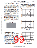
Since MMA2200W is fully signal–conditioned by its internal
op–amp and temperature compensation, the output of the
accelerometer can be directly interfaced with an analog–to–
digital (A/D) converter for digitization. A filter consists of one
RC network should be added if the connection between the
output of the accelerometer and the A/D converter is a long
track orcable. Thisstraycapacitancemaychangetheposition
oftheinternalpolewhichwoulddrivetheoutputamplifierofthe
accelerometer into oscillation or unstability. In this design, the
cut–off frequency is chosen to be 15.9 kHz which also acts as
an anti–alias filter for the A/D converter. The 3dB frequency
can be approximated by the following equation.
1
f
–3dB
2πRC
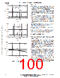
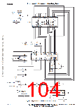
SOFTWARE DESCRIPTION
Referring to the schematic, Figure 3, the MMA2200W
accelerometer is connected to PORT D bit 5 and the output of
the amplifier is connected to PORT D bit 6 of the micro-
controller. This port is an input to the on–chip 8–bit analog–to–
digital (A/D) converter. Typically, the accelerometer provides
asignaloutputtothemicroprocessorofapproximately0.3Vdc
at –55g to 4.7 Vdc at +55g of acceleration. However, Motorola
only guarantees the accuracy within ±40g range. Using the
same reference voltage for the A/D converter and accelerom-
eterminimizesthenumberofadditionalcomponents, butdoes
sacrifice resolution. The resolution is defined by the following:
Upon power–up the system, the LCD will display CAL for
approximately 4 seconds. During this period, the output of the
accelerometer are sampled and averaged to obtain the zero
offset voltage or zero acceleration. This value will be saved in
the RAM which is used by the equation below to calculate the
impact in term of g–force. One point to note is that the
accelerometer should remain stationary during the zero
calibration.
Impact
[count count
]
resolution
offset
V
out
5
count
255
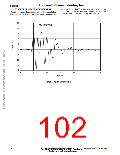
In this software program, the output of the accelerometer is
calculated every 650µs. During an impact, the peak decelera-
tion is measured and displayed on the LCD for 3 seconds
before resetting it to zero. In the mean time, if a higher impact
is detected, the value on the LCD will be updated accordingly.
However, when a low g is detected (e.g. 1.0g), the value will
not be displayed. Instead, more samples will be taken for
further averaging to eliminate the random noise and high
frequency component. Due to the fact that tilting is a low g and
low frequency signal, large number of sampling is preferred to
avoid unstable display. Moreover, the display value is not hold
for 3 seconds as in the case of an impact.
The count at 0g = [2.5/5]
The count at +25g = [3.5/5]
The count at –25g = [1.5/5]
255 128
255 179
255 77
Therefore the resolution 0.5g/count
The output of the accelerometer is ratiometric to the voltage
applied to it. The accelerometer and the reference voltages
are connected to a common supply; this yields a system that
is ratiometric. By nature of this ratiometric system, variations
in the voltage of the power supplied to the system will have no
effect on the system accuracy.
The liquid crystal display (LCD) is directly driven from I/O
ports A, B, and C on the microcontroller. The operation of a
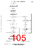
Figure 4 is a flowchart for the program that controls the
system.
Motorola Sensor Device Data
www.motorola.com/semiconductors
2–67
For More Information On This Product,
Go to: www.freescale.com

 MOTOROLA [ MOTOROLA ]