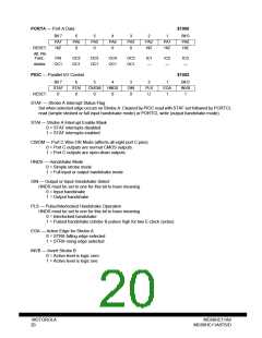
PORTA — Port A Data
$1000
Bit 7
6
5
PA5
0
4
PA4
0
3
PA3
0
2
1
Bit 0
PA0
HiZ
PA7
HiZ
PA6
0
PA2
HiZ
PA1
HiZ
RESET:
Alt. Pin
Func.:
PAI
OC2
OC1
OC3
OC1
OC4
OC1
OC5
OC1
IC1
—
IC2
—
IC3
—
And/or:
OC1
PIOC — Parallel I/O Control
$1002
Bit 7
STAF
0
6
STAI
0
5
CWOM
0
4
HNDS
0
3
OIN
0
2
PLS
U
1
EGA
1
Bit 0
INVB
1
RESET:
STAF — Strobe A Interrupt Status Flag
Set when selected edge occurs on Strobe A. Cleared by PIOC read with STAF set followed by PORTCL
read (simple strobed or full input handshake mode) or PORTCL write (output handshake mode).
STAI — Strobe A Interrupt Enable Mask
0 = STAF interrupts disabled
1 = STAF interrupts enabled
CWOM — Port C Wire-OR Mode (affects all eight port C pins)
0 = Port C outputs are normal CMOS outputs
1 = Port C outputs are open-drain outputs
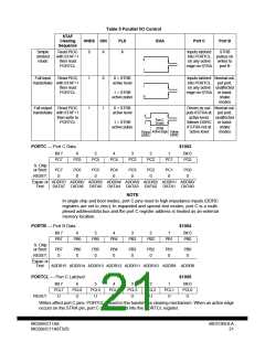
HNDS — Handshake Mode
0 = Simple strobe mode
1 = Full input or output handshake mode
OIN — Output or Input Handshake Select
HNDS must be set to one for this bit to have meaning.
0 = Input handshake
1 = Output handshake
PLS — Pulse/Interlocked Handshake Operation
HNDS must be set to one for this bit to have meaning.
0 = Interlocked handshake
1 = Pulsed handshake (strobe B pulses high for two E-clock cycles)
EGA — Active Edge for Strobe A
0 = STRA falling edge selected
1 = STRA rising edge selected
INVB — Invert Strobe B
0 = Active level is logic zero
1 = Active level is logic one
MOTOROLA
20
MC68HC11A8
MC68HC11A8TS/D

 MOTOROLA [ MOTOROLA ]