MITSUBISHI <INTELLIGENT POWER MODULES>
PM30CNJ060
FLAT-BASE TYPE
INSULATED PACKAGE
P
V
UP1
4
2
3
19
Vcc
In
OUT
Si
+
+
+
+
NC
V
V
V
D1
D2
D3
U
P
-
U
1
V
UPC
GND GND
21
8
6
7
V
VP1
Vcc
OUT
NC
Si
In
V
P
V
5
V
VPC
GND GND
M
22
12
10 NC
V
WP1
Vcc
OUT
Si
In
11
9
WP
W
V
WPC
GND GND
23
+
+
UN
UN
OUN
SUN
N
VN
20
VN
WN
OVN
SVN
WN
Fo
Fo
OWN
SWN
VN1
Vcc
+
V
D4
VNC
GND
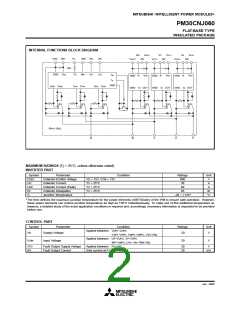
Fig. 8 Application Example Circuit
NOTES FOR STABLE AND SAFE OPERATION ;
Design the PCB pattern to minimize wiring length between opto-coupler and IPM’s input terminal, and also to minimize the
•
stray capacity between the input and output wirings of opto-coupler.
Connect low impedance capacitor between the Vcc and GND terminal of each fast switching opto-coupler.
•
Fast switching opto-couplers : tPLH, tPHL ≤ 0.8µs, Use High CMR type.
•
Slow switching opto-coupler : CTR > 100%
•
Use 4 isolated control power supplies (VD). Also, care should be taken to minimize the instantaneous voltage charge of the
•
power supply.
Make inductance of DC bus line as small as possible, and minimize surge voltage using snubber capacitor between P and N
•
terminal.
Use line noise filter capacitor (ex. 4.7nF) between each input AC line and ground to reject common-mode noise from AC line
•
and improve noise immunity of the system.
Jan. 2000

 MITSUBISHI [ Mitsubishi Group ]