MITSUBISHI <INTELLIGENT POWER MODULES>
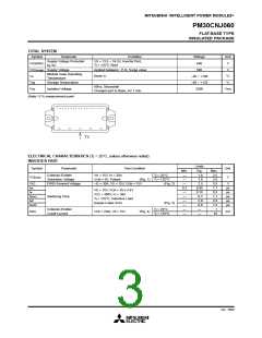
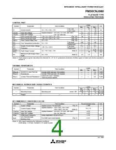
PM30CNJ060
FLAT-BASE TYPE
INSULATED PACKAGE
PRECAUTIONS FOR TESTING
1. Before appling any control supply voltage (VD), the input signals should be low level.
After this, each input signal should be set to the specified ON and OFF level.
2. When performing “SC” tests, the turn-off surge voltage spike at the corresponding protection operation should not be
allowed to rise above VCC(surge) rating of the device.
(These test should not be done by using a curve tracer or its equivalent.)
P, (U,V,W)
V
P, (U,V,W)
Ic
–Ic
V
V
CIN
(0V)
V
CIN
(15V)
U,V,W, (N)
U,V,W, (N)
VD (all)
VD (all)
Fig. 1 VCE(sat) Test
Fig. 2 VEC Test
a) Lower Arm Switching
P
trr
Vce
Signal input
(Upper Arm)
Irr
Ic
U,V,W
Vcc
90%
Signal input
(Lower Arm)
90%
V
CIN
N
P
10%
VD (all)
Ic
10%
b) Upper Arm Switching
tc (on)
tc (off)
td (off)
V
CIN
Signal input
(Upper Arm)
VCIN
U,V,W
Vcc
td (on)
tr
tf
Signal input
(Lower Arm)
ton= td (on) + tr
toff= td (off) + tf
N
Ic
VD (all)
Fig. 3 Switching time Test circuit and waveform
P, (U,V,W)
A
V
CIN
Signal Input
V
(15V)
CIN
Pulse
V
CE
Over Current (oc)
OC
U,V,W, (N)
Constant Current
I
C
V
D (all)
t
off (OC)
Fig. 4 ICES Test
P, (U,V,W)
Short Over Current (sc)
Signal Input
V
CC
V
CIN
SC
Constant Current
I
C
U,V,W, (N)
VD (all)
IC
t
off (OC)
Fig. 5 OC and SC Test
Fig. 6 OC and SC Test waveform
P
V
D
V
V
CINP
U,V,W
Vcc
V
D
CINN
N
Ic
VCINP
0V
0V
t
t
V
CINN
t
dead
t
dead
Fig. 7 Dead time measurement point example
Jan. 2000

 MITSUBISHI [ Mitsubishi Group ]