MITSUBISHI <INTELLIGENT POWER MODULES>
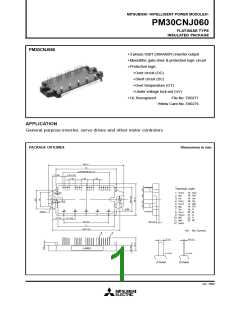
PM30CNJ060
FLAT-BASE TYPE
INSULATED PACKAGE
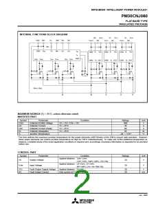
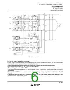
INTERNAL FUNCTIONS BLOCK DIAGRAM
W
P
V
WP1
VP
VVP1
UP
VUP1
VNC VN1
Fo
WN VN
UN
VWPC
NC
VVPC
NC
VUPC
NC
Rfo
GND Vcc
Fo
W
N
VN
UN
Tb
In
Vcc
In
Vcc
In
GND
Vcc
GND
GND
Tc
GND
S
WN
O
WN
SVN
O
VN
SUN
OUN
GND Si OUT
GND Si OUT
GND Si OUT
Rfo=1.5kΩ
N
W
V
U
P
MAXIMUM RATINGS (Tj = 25°C, unless otherwise noted)
INVERTER PART
Symbol
VCES
±IC
Parameter
Collector-Emitter Voltage
Collector Current
Condition
Ratings
600
30
Unit
V
VD = 15V, VCIN = 15V
TC = 25°C
A
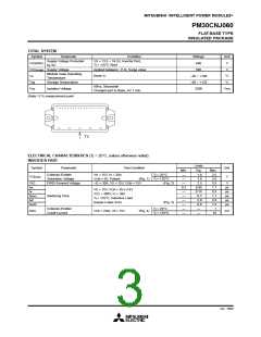
±ICP
PC
Collector Current (Peak)
Collector Dissipation
Junction Temperature
TC = 25°C
60
A
TC = 25°C
83
W
°C
Tj
–20 ~ +125
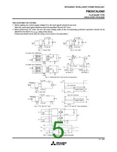
The item defines the maximum junction temperature for the power elements (IGBT/Diode) of the IPM to ensure safe operation. However,
these power elements can endure junction temperature as high as 150°C instantaneously. To make use of this additional temperature al-
lowance, a detailed study of the exact application conditions is required and, accordingly, necessary information is requested to be provided
before use.
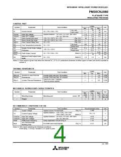
CONTROL PART
Symbol
Parameter
Supply Voltage
Condition
Applied between : VUP1-VUPC
VVP1-VVPC, VWP1-VWPC, VN1-VNC
Applied between : UP-VUPC, VP-VVPC
WP-VWPC, UN • VN • WN-VNC
Applied between : FO-VNC
Sink current at FO terminals
Ratings
20
Unit
V
VD
VCIN
Input Voltage
20
V
VFO
IFO
Fault Output Supply Voltage
Fault Output Current
20
20
V
mA
Jan. 2000

 MITSUBISHI [ Mitsubishi Group ]