MITSUBISHI MICROCOMPUTERS
3827 Group
SINGLE-CHIP 8-BIT CMOS MICROCOMPUTER
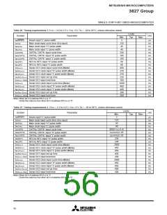
Table 14 Recommended operating conditions (Mask ROM version) (VCC = 2.2 to 5.5 V, Ta = –20 to 85°C, unless otherwise noted)
Limits
Symbol
Parameter
Test conditions
(4.0 V ≤ VCC ≤ 5.5 V)
Unit
MHz
MHz
Min.
Typ.
Max.
4.0
f(CNTR0)
f(CNTR1)
Input frequency for timers X and Y
(duty cycle 50%)
(10✕VCC
(2.2 V ≤ VCC ≤ 4.0 V)
–4)/9
High-speed mode
(4.0 V ≤ VCC ≤ 5.5 V)
8.0
MHz
Main clock input oscillation frequency
(Note 1)
f(XIN)
High-speed mode
(2.2 V ≤ VCC ≤ 4.0 V)
(20✕VCC
MHz
–8)/9
Middle-speed mode
8.0
50
MHz
kHz
f(XCIN)
Sub-clock input oscillation frequency (Notes 1, 2)
32.768
Notes1: When the oscillation frequency has a duty cycle of 50%.
2: When using the microcomputer in low-speed mode, make sure that the sub-clock input oscillation frequency on condition that f(XCIN) < f(XIN)/3.
Table 15 Recommended operating conditions (PROM version) (VCC = 2.5 to 5.5 V, Ta = –20 to 85°C, unless otherwise noted)
Limits
Symbol
Parameter
Test conditions
(4.0 V ≤ VCC ≤ 5.5 V)
Unit
MHz
MHz
Min.
Typ.
Max.
4.0
f(CNTR0)
f(CNTR1)
Input frequency for timers X and Y
(duty cycle 50%)
(2✕VCC)
(2.5 V ≤ VCC ≤ 4.0 V)
–4
High-speed mode
(4.0 V ≤ VCC ≤ 5.5 V)
8.0
MHz
Main clock input oscillation frequency
(Note 1)
f(XIN)
High-speed mode
(2.5 V ≤ VCC ≤ 4.0 V)
(4✕VCC)
MHz
–8
Middle-speed mode
8.0
50
MHz
kHz
f(XCIN)
Sub-clock input oscillation frequency (Notes 1, 2)
32.768
Notes1: When the oscillation frequency has a duty cycle of 50%.
2: When using the microcomputer in low-speed mode, make sure that the sub-clock input oscillation frequency on condition that f(XCIN) < f(XIN)/3.
52

 MITSUBISHI [ Mitsubishi Group ]