MITSUBISHI MICROCOMPUTERS
3827 Group
SINGLE-CHIP 8-BIT CMOS MICROCOMPUTER
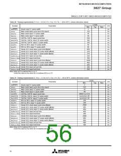
Table 18 A-D converter characteristics
(VCC = 2.2 to 5.5 V, VSS = 0 V, Ta = –20 to 85°C, 4 MHz ≤ f(XIN) ≤ 8 MHz, in middle/high-speed mode unless otherwise noted)
Limits
Symbol
Parameter
Test conditions
Unit
Min.
Typ.
Max.
10
–
–
Resolution
Bits
LSB
LSB
Absolute accuracy
(excluding quantization error)
VCC ≥ VREF = 4 V
±2.5
±4.0
VCC ≥ VREF = 2.7 V
31
(Note)
tCONV
Conversion time
f(XIN) = 4 MHz
30.5
50
µs
RLADDER
IVREF
IIA
Ladder resistor
35
150
0.5
kΩ
µA
µA
200
5.0
Reference power source input current
Analog port input current
VREF = 5 V
Note: When an internal trigger is used in middle-speed mode, it is 34 µs.
Table 19 D-A converter characteristics
(VCC = 2.2 to 5.5 V, VCC = VREF, VSS = AVSS = 0 V, Ta = –20 to 85°C, in middle/high-speed mode unless otherwise noted)
Limits
Symbol
Parameter
Test conditions
Unit
Min.
Typ.
Max.
8
–
–
Bits
%
Resolution
1.0
2.0
VCC = VREF = 5 V
Absolute accuracy
VCC = VREF = 2.7 V
%
Setting time
µs
tsu
3
Output resistor
1
4
kΩ
mA
RO
2.5
(Note)
IVREF
Reference power source input current
6.0
Note: Using one D-A converter, with the value in the D-A conversion register of the other D-A converter being “0016”, and excluding currents flowing through
the A-D resistance ladder.
55

 MITSUBISHI [ Mitsubishi Group ]