MITSUBISHI MICROCOMPUTERS
3827 Group
SINGLE-CHIP 8-BIT CMOS MICROCOMPUTER
INTERRUPTS
Interrupts occur by seventeen sources: seven external, nine inter-
Interrupt Operation
Upon acceptance of an interrupt the following operations are auto-
nal, and one software.
matically performed:
1. The contents of the program counter and processor status
register are automatically pushed onto the stack.
2. The interrupt disable flag is set and the corresponding
interrupt request bit is cleared.
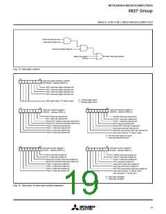
Interrupt Control
Each interrupt except the BRK instruction interrupt have both an
interrupt request bit and an interrupt enable bit, and is controlled
by the interrupt disable flag. An interrupt occurs if the correspond-
ing interrupt request and enable bits are “1” and the interrupt
disable flag is “0.” Interrupt enable bits can be set or cleared by
software. Interrupt request bits can be cleared by software, but
cannot be set by software. The BRK instruction interrupt and reset
cannot be disabled with any flag or bit. The I flag disables all inter-
rupts except the BRK instruction interrupt and reset. If several
interrupts requests occurs at the same time the interrupt with high-
est priority is accepted first.
3. The interrupt jump destination address is read from the vec-
tor table into the program counter.
■Notes
When the active edge of an external interrupt (INT0–INT2, CNTR0,
CNTR1) is set or when switching interrupt sources of ADT/A-D
conversion interrupt, the corresponding interrupt request bit may
also be set. Therefore, take following sequence:
(1) Disable the external interrupt which is selected.
(2) Change the active edge in interrupt edge selection register
(timer XY mode register when using CNTR0, CNTR1)
(3) Clear the set interrupt request bit to “0.”
(4) Enable the external interrupt which is selected.
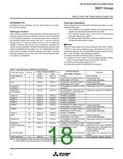
Table 6 Interrupt vector addresses and priority
Interrupt Request
Remarks
Vector Addresses (Note 1)
Interrupt Source
Priority
High
Low
Generating Conditions
Reset (Note 2)
At reset
1
2
FFFD16
FFFB16
FFFC16
FFFA16
Non-maskable
INT0
At detection of either rising or
falling edge of INT0 input
External interrupt
(active edge selectable)
At detection of either rising or
falling edge of INT1 input
INT1
3
4
FFF916
FFF716
FFF816
FFF616
External interrupt
(active edge selectable)
Serial I/O1
reception
At completion of serial I/O1 data Valid when serial I/O1 is selected
reception
At completion of serial I/O1
transmit shift or when transmis-
sion buffer is empty
Serial I/O1
transmission
5
FFF516
FFF416
Valid when serial I/O1 is selected
Timer X
6
7
FFF316
FFF116
FFEF16
FFED16
FFEB16
FFF216
FFF016
FFEE16
FFEC16
FFEA16
At timer X underflow
At timer Y underflow
At timer 2 underflow
At timer 3 underflow
Timer Y
Timer 2
Timer 3
8
9
CNTR0
At detection of either rising or
falling edge of CNTR0 input
10
External interrupt
(active edge selectable)
At detection of either rising or
falling edge of CNTR1 input
CNTR1
11
FFE916
FFE816
External interrupt
(active edge selectable)
FFE616
FFE416
At timer 1 underflow
Timer 1
INT2
12
13
FFE716
FFE516
At detection of either rising or External interrupt
falling edge of INT2 input
(active edge selectable)
Serial I/O2
At completion of serial I/O2 data
transmission or reception
14
15
16
FFE316
FFE116
FFDF16
FFE216
FFE016
FFDE16
Valid when serial I/O2 is selected
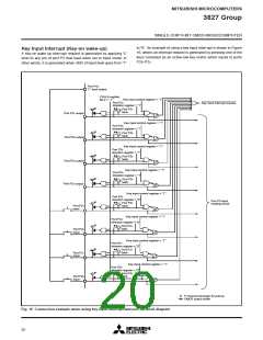
Key input
(Key-on wake-up)
At falling of conjunction of input External interrupt
level for port P2 (at input mode)
(valid when an “L” level is applied)
Valid when ADT interrupt is se-
lected External interrupt
(Valid at falling)
ADT
At falling of ADT input
A-D conversion
BRK instruction
At completion of A-D conversion
At BRK instruction execution
Valid when A-D interrupt is se-
lected
17
FFDD16
FFDC16
Non-maskable software interrupt
Notes1: Vector addresses contain interrupt jump destination addresses.
2: Reset function in the same way as an interrupt with the highest priority.
18

 MITSUBISHI [ Mitsubishi Group ]