MITSUBISHI MICROCOMPUTERS
3822 Group
SINGLE-CHIP 8-BIT CMOS MICROCOMPUTER
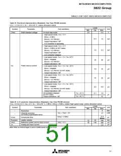
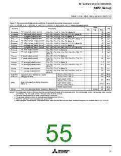
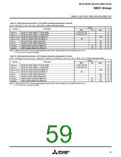
Table 27 Recommended operating conditions (Extended operating temperature version)
(VCC = 2.0 to 5.5 V, Ta = –20 to 85 °C, and VCC = 3.0 to 5.5 V, Ta = –40 to –20° C, unless otherwise noted)
Limits
Typ.
Symbol
Parameter
Unit
Min.
Max.
–40
–40
40
“H” total peak output current
“H” total peak output current
“L” total peak output current
“L” total peak output current
“H” total average output current
“H” total average output current
“L” total average output current
“L” total average output current
“H” peak output current
ΣIOH(peak)
ΣIOH(peak)
ΣIOL(peak)
ΣIOL(peak)
ΣIOH(avg)
ΣIOH(avg)
ΣIOL(avg)
ΣIOL(avg)
IOH(peak)
IOH(peak)
P00–P07, P10–P17, P20–P27 (Note 1)
P41–P47, P50–P57, P60–P67, P70, P71 (Note 1)
P00–P07, P10–P17, P20–P27 (Note 1)
P41–P47, P50–P57, P60–P67, P70, P71 (Note 1)
P00–P07, P10–P17, P20–P27 (Note 1)
P41–P47, P50–P57, P60–P67, P70, P71 (Note 1)
P00–P07, P10–P17, P20–P27 (Note 1)
P41–P47, P50–P57, P60–P67, P70, P71 (Note 1)
P00–P07, P10–P17 (Note 2)
mA
mA
mA
mA
mA
mA
mA
mA
mA
mA
40
–20
–20
20
20
–2
“H” peak output current
–5
P20–P27, P41–P47, P50–P57, P60–P67, P70, P71
(Note 2)
IOL(peak)
IOL(peak)
“L” peak output current
“L” peak output current
P00–P07, P10–P17 (Note 2)
5
mA
mA
P20–P27, P41–P47, P50–P57, P60–P67, P70, P71
10
(Note 2)
–1.0
–2.5
mA
mA
IOH(avg)
IOH(avg)
“H” average output current
“H” average output current
P00–P07, P10–P17 (Note 3)
P20–P27, P41–P47, P50–P57, P60–P67, P70, P71
(Note 3)
2.5
5.0
mA
mA
“L” average output current
“L” average output current
IOL(avg)
IOL(avg)
P00–P07, P10–P17 (Note 3)
P20–P27, P41–P47, P50–P57, P60–P67, P70, P71
(Note 3)
(4.0 V ≤ VCC ≤ 5.5 V)
(2.0 V ≤ VCC ≤ 4.0 V)
4.0
MHz
MHz
f(CNTR0)
f(CNTR1)
Input frequency for timers X and Y
(duty cycle 50%)
VCC
High-speed mode
(4.0 V ≤ VCC ≤ 5.5 V)
8.0
MHz
Main clock input oscillation frequency
(Note 4)
f(XIN)
High-speed mode
(2.0 V ≤ VCC ≤ 4.0 V)
2ꢀVCC MHz
Middle-speed mode
8.0
50
MHz
kHz
f(XCIN)
Sub-clock input oscillation frequency (Notes 4, 5)
32.768
Notes 1: The total output current is the sum of all the currents flowing through all the applicable ports. The total average current is an average value mesured
over 100 ms. The total peak current is the peak value of all the currents.
2: The peak output current is the peak current flowing in each port.
3: The average output current is an average value measured over 100 ms.
4: When the oscillation frequency has a duty cycle of 50 %.
5: When using the microcomputer in low-speed mode, make sure that the sub-clock input oscillation frequency on condition that f(XCIN) < f(XIN)/3.
55

 MITSUBISHI [ Mitsubishi Group ]