Mitsubishi microcomputers
M16C / 62 Group
SINGLE-CHIP 16-BIT CMOS MICROCOMPUTER
Appendix Standard Serial I/O Mode (Flash Memory Version)
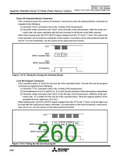
ID Check
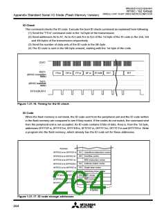
This command checks the ID code. Execute the boot ID check command as explained here following.
(1) Send the “F516” command code in the 1st byte of the transmission.
(2) Send addresses A0 to A7, A8 to A15 and A16 to A23 of the 1st byte of the ID code in the 2nd, 3rd
and 4th bytes of the transmission respectively.
(3) Send the number of data sets of the ID code in the 5th byte.
(4) The ID code is sent in the 6th byte onward, starting with the 1st byte of the code.
CLK1
RxD1
ID size
ID1
ID7
F516
DF16
FF16
0F16
(M16C reception
data)
TxD1
(M16C transmit
data)
RTS1(BUSY)
Figure 1.31.16. Timing for the ID check
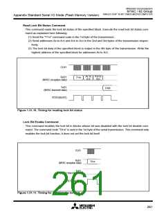
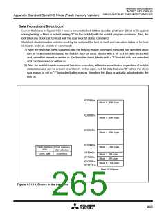
ID Code
When the flash memory is not blank, the ID code sent from the peripheral unit and the ID code written
in the flash memory are compared to see if they match. If the codes do not match, the command sent
from the peripheral unit is not accepted. An ID code contains 8 bits of data. Area is, from the 1st byte,
addresses 0FFFDF16, 0FFFE316, 0FFFEB16, 0FFFEF16, 0FFFF316, 0FFFF716 and 0FFFFB16. Write
a program into the flash memory, which already has the ID code set for these addresses.
Address
ID1 Undefined instruction vector
ID2 Overflow vector
0FFFDC16 to 0FFFDF16
0FFFE016 to 0FFFE316
0FFFE416 to 0FFFE716
0FFFE816 to 0FFFEB16
0FFFEC16 to 0FFFEF16
0FFFF016 to 0FFFF316
0FFFF416 to 0FFFF716
0FFFF816 to 0FFFFB16
0FFFFC16 to 0FFFFF16
BRK instruction vector
ID3 Address match vector
ID4 Single step vector
ID5 Watchdog timer vector
ID6 DBC vector
ID7 NMI vector
Reset vector
4 bytes
Figure 1.31.17. ID code storage addresses
264

 MITSUBISHI [ Mitsubishi Group ]