Mitsubishi microcomputers
M16C / 61 Group
SINGLE-CHIP 16-BIT CMOS MICROCOMPUTER
Status Transition Of BCLK
Status Transition Of BCLK
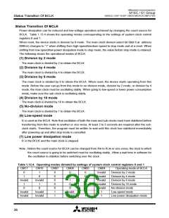
Power dissipation can be reduced and low-voltage operation achieved by changing the count source for
BCLK. Table 1.13.4 shows the operating modes corresponding to the settings of system clock control
registers 0 and 1.
When reset, the device starts in division by 8 mode. The main clock division select bit 0(bit 6 at address
000616) changes to “1” when shifting from high-speed/medium-speed to stop mode and at a reset. When
shifting from low-speed/low power dissipation mode to stop mode, the value before stop mode is retained.
The following shows the operational modes of BCLK.
(1) Division by 2 mode
The main clock is divided by 2 to obtain the BCLK.
(2) Division by 4 mode
The main clock is divided by 4 to obtain the BCLK.
(3) Division by 8 mode
The main clock is divided by 8 to obtain the BCLK. When reset, the device starts operating from this
mode. Before the user can go from this mode to no division mode, division by 2 mode, or division by 4
mode, the main clock must be oscillating stably. When going to low-speed or lower power consumption
mode, make sure the sub-clock is oscillating stably.
(4) Division by 16 mode
The main clock is divided by 16 to obtain the BCLK.
(5) No-division mode
The main clock is divided by 1 to obtain the BCLK.
(6) Low-speed mode
fC is used as the BCLK. Note that oscillation of both the main and sub-clocks must have stabilized before
transferring from this mode to another or vice versa. At least 2 to 3 seconds are required after the sub-
clock starts. Therefore, the program must be written to wait until this clock has stabilized immediately
after powering up and after stop mode is cancelled.
(7) Low power dissipation mode
fC is the BCLK and the main clock is stopped.
Note : Before the count source for BCLK can be changed from XIN to XCIN or vice versa, the clock to which
the count source is going to be switched must be oscillating stably. Allow a wait time in software for
the oscillation to stabilize before switching over the clock.
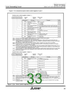
Table 1.12.4. Operating modes dictated by settings of system clock control registers 0 and 1
CM17
CM16
CM07
CM06
CM05
CM04
Invalid
Invalid
Invalid
Invalid
Invalid
1
Operating mode of BCLK
Division by 2 mode
0
1
1
0
0
0
0
0
0
1
1
0
0
0
0
0
0
0
1
0
Division by 4 mode
Invalid
1
Invalid
1
1
0
Division by 8 mode
Division by 16 mode
No-division mode
0
0
0
Invalid
Invalid
Invalid
Invalid
Invalid
Invalid
Low-speed mode
1
Low power dissipation mode
36

 MITSUBISHI [ Mitsubishi Group ]