Mitsubishi microcomputers
M16C / 61 Group
SINGLE-CHIP 16-BIT CMOS MICROCOMPUTER
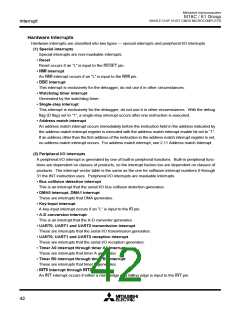
Power control
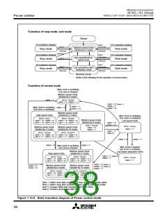
Transition of stop mode, wait mode
Reset
All oscillators stopped
CPU operation stopped
WAIT
instruction
CM10 = “1”
Interrupt
Medium-speed mode
(divided-by-8 mode)
Stop mode
Wait mode
Interrupt
Interrupt
WAIT
instruction
All oscillators stopped
CPU operation stopped
High-speed/medium-
speed mode
CM10 = “1”
Stop mode
Wait mode
Interrupt
WAIT
instruction
All oscillators stopped
CPU operation stopped
CM10 = “1”
Interrupt
Low-speed/low power
dissipation mode
Stop mode
Wait mode
Interrupt
Normal mode
(Refer to the following for the transition of normal mode.)
Transition of normal mode
Main clock is oscillating
Sub clock is stopped
Medium-speed mode
(divided-by-8 mode)
CM06 = “1”
BCLK : f(XIN)/8
CM07 = “0” CM06 = “1”
CM07 = “0” (Note 1)
CM06 = “1”
CM04 = “0”
CM04 = “1”
(Notes 1, 3)
Main clock is oscillating
Sub clock is oscillating
CM04 = “0”
Medium-speed mode
(divided-by-2 mode)
High-speed mode
Main clock is oscillating
Sub clock is oscillating
BCLK : f(XIN
CM07 = “0” CM06 = “0”
CM17 = “0” CM16 = “0”
)
BCLK : f(XIN)/2
CM07 = “0” CM06 = “0”
CM17 = “0” CM16 = “1”
Medium-speed mode
(divided-by-8 mode)
Low-speed mode
CM07 = “0”
(Note 1, 3)
BCLK : f(XIN)/8
CM07 = “0”
CM06 = “1”
BCLK : f(XCIN
CM07 = “1”
)
Medium-speed mode
(divided-by-4 mode)
Medium-speed mode
(divided-by-16 mode)
CM07 = “1”
(Note 2)
BCLK : f(XIN)/4
CM07 = “0” CM06 = “0”
CM17 = “1” CM16 = “0”
BCLK : f(XIN)/16
CM07 = “0” CM06 = “0”
CM17 = “1” CM16 = “1”
CM05 = “0”
CM05 = “1”
CM04 = “0”
CM04 = “1”
Main clock is oscillating
Sub clock is stopped
Main clock is stopped
Sub clock is oscillating
Low power dissipation mode
Medium-speed mode
(divided-by-2 mode)
High-speed mode
CM07 = “1” (Note 2)
CM05 = “1”
BCLK : f(XIN
CM07 = “0” CM06 = “0”
CM17 = “0” CM16 = “0”
)
BCLK : f(XIN)/2
CM07 = “0” CM06 = “0”
CM17 = “0” CM16 = “1”
BCLK : f(XCIN
CM07 = “1”
)
CM07 = “0” (Note 1)
CM06 = “0” (Note 3)
CM04 = “1”
Medium-speed mode
(divided-by-4 mode)
Medium-speed mode
(divided-by-16 mode)
CM06 = “0”
(Notes 1,3)
BCLK : f(XIN)/4
BCLK : f(XIN)/16
CM07 = “0” CM06 = “0”
CM17 = “1” CM16 = “0”
CM07 = “0” CM06 = “0”
CM17 = “1” CM16 = “1”
Note 1: Switch clock after oscillation of main clock is sufficiently stable.
Note 2: Switch clock after oscillation of sub clock is sufficiently stable.
Note 3: Change CM06 after changing CM17 and CM16.
Note 4: Transit in accordance with arrow.
Figure 1.12.5. State transition diagram of Power control mode
38

 MITSUBISHI [ Mitsubishi Group ]