Mitsubishi microcomputers
M16C / 61 Group
SINGLE-CHIP 16-BIT CMOS MICROCOMPUTER
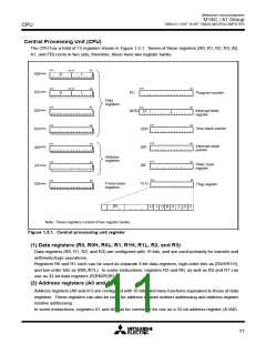
Reset
____________
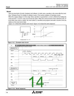
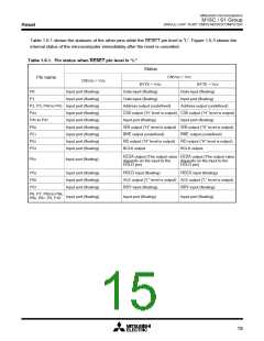
Table 1.6.1 shows the statuses of the other pins while the RESET pin level is “L”. Figure 1.6.3 shows the
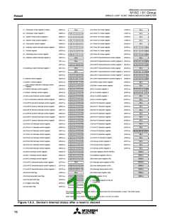
internal status of the microcomputer immediately after the reset is cancelled.
____________
Table 1.6.1. Pin status when RESET pin level is “L”
Status
CNVSS = VCC
Pin name
CNVSS = VSS
BYTE = VSS
Data input (floating)
BYTE = VCC
Data input (floating)
P0
P1
Input port (floating)
Input port (floating)
Data input (floating)
Input port (floating)
P2, P3, P40 to P43 Input port (floating)
Address output (undefined)
Address output (undefined)
P44
Input port (floating)
Input port (floating)
Input port (floating)
Input port (floating)
Input port (floating)
Input port (floating)
CS0 output (“H” level is output) CS0 output (“H” level is output)
Input port (floating) Input port (floating)
WR output (“H” level is output) WR output (“H” level is output)
BHE output (undefined) BHE output (undefined)
RD output (“H” level is output) RD output (“H” level is output)
BCLK output BCLK output
P45 to P47
P50
P51
P52
P53
HLDA output (The output value HLDA output (The output value
P54
Input port (floating)
depends on the input to the
HOLD pin)
depends on the input to the
HOLD pin)
P55
P56
P57
Input port (floating)
Input port (floating)
Input port (floating)
HOLD input (floating)
HOLD input (floating)
ALE output (“L” level is output) ALE output (“L” level is output)
RDY input (floating)
Input port (floating)
RDY input (floating)
Input port (floating)
P6, P7, P80 to P84,
P86, P87, P9, P10
Input port (floating)
15

 MITSUBISHI [ Mitsubishi Group ]