PDSP16510A MA
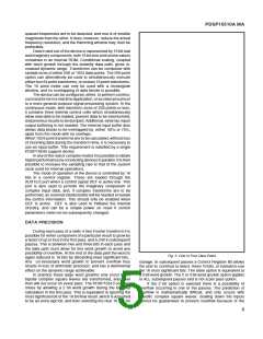
complete or DAV will never go active. See the section on
multiple device operation.
transforms, and their concurrent derivatives, the location of
the low going edge in the data steam is dependent on the
amount of block overlapping. The low going edge transition
must be provided after 64 samples have been loaded with
75% overlapping, and after 128 samples have been loaded
with 50% overlapping. With no overlapping the edge must be
provided after 256 samples have been loaded.
In a single device system with Bit 12 set, INEN can be
taken high to inhibit the load operation when gaps occur in the
data stream. In the INEN edge activated mode gaps in the
data stream can only be accommodated if the DIS clock is
externally inhibited. Taking INEN high will not inhibit the
loading of data in this mode.
Withgaps inthedatastreamthepeaksamplingratescan
be higher than continuous sampling rates. When data loading
is not coincident with transform operations the peak rate can
equal that of the system clock, otherwise it is reduced by the
factor, F, given on the opposite page.
When Control Register Bit 12 is set in any multiple device
mode, the DEF high going edge will also initiate a load
operationafterithasbeeninternallysynchronisedtotherising
DIS edge. If the first device in a multiple device system is
programmed in this manner, the transform sequence will
automatically start when DEF goes in-active. The other de-
vices need the INEN edge as usual, and must have Bit 12
reset. A fuller explanation of the use of Bit 12 in a multiple
device mode is given in the section on I/O In Multiple Device
Systems. Note that the use of Bit 12 in a single device system
( Control Register Bits 10:9 = 00) is completely different to its
use in a multiple device mode.
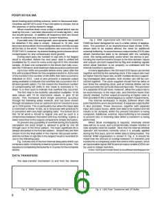
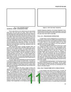
LOADING DATA
Data loading is controlled by three signals; DIS an input
strobe, INEN aloadenable, andLFLG an outputflag. Detailed
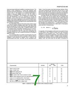
timing information is given in Table 1. Once sufficient data has
beenacquired,atransformwillautomaticallycommence.This
is normally after a complete block has been loaded, except
when a single device is performing overlapped transforms of
256 points or less. With 75% overlapping, transforms will
commence after 25% of a new block has been loaded, and
with 50% overlapping transforms commence after 50% of the
data has been loaded. The remainder of the block is provided
by data already stored in the internal RAM.
The data strobe is used to load data into the internal
workspace RAM, and data must meet the specified set up and
hold times with respect to its rising edge. This strobe can be
asynchronous to the system clock used internally, and the
device will perform the necessary internal synchronisation.
DIScanbeacontinuousinputsincethedeviceonlyloadsdata
when an input enabling signal is active.
An internal synchronisation interval is necessary be-
tween the last sample being loaded with the DIS strobe and
transformsbeingstartedwiththesystemclock. Thiscanbeup
to twelve system clock periods when data transfers and
transforms are overlapped. The transform times given later in
Table 4 are maximum values, and include these twelve
periods.
The way in which the INEN signal controls data loading
is dependent on whether a single or multiple device is to be
implemented, and the status of Control Register Bit 12.
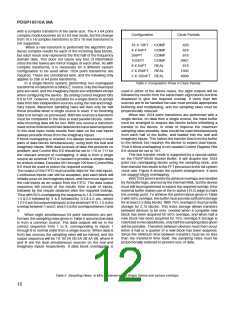
When Bit12 is set in a SINGLE device system the INEN
signal is simply used as an enable for the DIS strobes. When
INEN is low, and provided the relevant set up and hold times
have been satisfied, data will be loaded with the rising edge of
the DIS strobe. If no gaps occur within the incoming data,
INEN can be tied permanently low, provided that the sampling
rate has been chosen such that transforms are completed
before a new block of data is loaded. For transforms of less
than 1024 points, data will then be continually processed
without any loss of information. In the 1024 point modes the
device will cease loading data when 1024 samples have been
loaded, and even if INEN remains low no more data will be
accepted until the previous results have been dumped.
In a multiple device system an edge is ALWAYS needed
to commence a load operation, and Bit 12 has a different
purpose. The edge is provided by INEN going low. Loading
will cease when a complete block (or group of blocks with
multipleconcurrenttransforms)ofdatahasbeenloaded,even
ifINENremainslow. INENmustgohighatsomepointafterthe
minimum hold time has been satisfied, and then return low
AFTER ALL DATA HAS BEEN LOADED, before a new load
operation can commence. Low going edges which occur
before all data has been loaded will be ignored.
TheLFLGoutputgoesactiveinresponsetotheDISrising
edge used to load the first data sample, and indicates that a
load operation is occurring. In an edge activated system the
LFLGoutputwillgohighastheresultofthefirsthighgoingDIS
edge after INEN has gone low. In the simple INEN enabling
mode, internal logic counts the number of valid inputs and
detects when the programmed block length has been
reached. LFLG then goes low and will go high again in
response to the next valid DIS strobe. LFLG will go low when
DEF is active and will go high in response to the first INEN
enabled DIS edge after DEF has gone in- active.
The active going LFLG edge does not normally have any
system significance, but in the block overlapping modes the
in-active going edge will occur when 50% or 75% of the data
hasbeenloaded. BydrivingtheINENinputononedevicewith
theLFLGoutputfromapreviousdevice,thisedgecanbeused
to partition data between several devices in a multiple device
system. It can also be used to provide an address marker for
a user defined input buffer, when executing 1024 point trans-
formswithasingledevice. Itisnotneeded,however,whenthe
input buffer is provided by the PDSP16540.
DUMPING DATA
Data output is controlled by an asynchronous output
strobe [DOS], a dump enable signal [DEN], and a Data
Availablesignal[DAV]. TheDAVsignalisusedtoindicatethat
the internal output buffer contains transformed data, and the
DEN input is used to control the outputing of that data. The
output buffer within the device is clocked by the DOS input,
and must be primed with four DOS strobes once a transform
iscompleteinordertotransferdatatotheoutputpins.DAVwill
The INEN edge mode is actually provided for the correct
operationofmultipledevicesystems,butifBit12intheControl
Register is reset in the SINGLE device mode, the edge
activated operation will still be possible. With all but 256 point
complextransforms,thesingledeviceedgemodeofoperation
is identical to that of a multiple device system. With 256 point
8

 MITEL [ MITEL NETWORKS CORPORATION ]