PDSP16510A MA
with a complex transform of the same size. The 4 x 64 point
complex mode becomes an 8 x 64 real mode, but the change
from 16 x 16 complex transforms to 32 x 16 real transforms is
not supported.
When a real transform is performed the algorithm pro-
duces complex results for each of the incoming data blocks,
but each result only represents the first half of the frequency
domain data. This does not cause any loss of information
since the two halves are mirror images of each other. As with
complex transforms, it is necessary for a different system
configuration to be used when 1024 point transforms are
required. These are considered later, and the following only
applies to 256 or 64 point transforms.
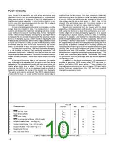
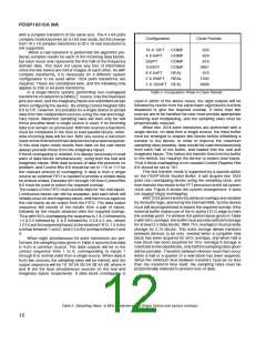
Configuration
Clock Periods
16 X 16PT
4 X 64PT
256PT
COMP
COMP
COMP
COMP
REAL
REAL
420
624
816
1024PT
3907
816
8 X 64PT
2 X 256PT
1032
4699
2 X 1024PT REAL
Table 4. Computation Times in Clock Periods
In a single device system, performing non overlapped
transformsondatafromaSINGLE source, onlytheRealinput
pins are used, and the Imaginary inputs are redundant except
when configuring the device. By setting Control Register Bits
8:6 to 101, however, it is possible for a single device to accept
data from two independent sources using the real and imagi-
nary inputs. Maximum sampling rates will then only be half
those possible when a single source is used, if no incoming
data is to remain un-processed. With two sources a transform
must be completed in the time to load parallel blocks, other-
wise incoming data will be lost. With one source a transform
neednotbefinisheduntiltwodatablockshavebeenacquired.
In this dual input mode results from data on the real inputs
always precede those from the imaginary inputs.
If block overlapping is needed, it is always necessary to load
pairs of data blocks simultaneously, using both the real and
imaginary inputs. With dual sources of data this presents no
problem, and Control Bits 8:6 should be set to 110 or 111 for
the relevant amount of overlapping. If data is from a single
source an external FIFO is needed to provide a simple delay
forablockofdata. Decodes001through100fromControlBits
8:6 must be used to select the required overlap.
The output of the FIFO must provide data for the real inputs.
Continuous inputs can still be accepted, and each block will
initiallyoccurontheimaginaryinputs, andthenoccuragainon
the real inputs as an output from the FIFO. The data output
sequence will consist of the results from a pair of inputs,
followed by the results obtained after the required overlap.
Thus with 50% overlapping the sequence is 1 & 2 followed by
1.5 & 2.5 followed by 3 & 4 followed by 3.5 & 4.5 etc., where
1 2 3 4 are the sequential inputs to the external FIFO, 1.5 is the
overlapbetween1and2, and2.5istheoverlapbetween2and
3.
When eight simultaneous 64 point transforms are per-
formed, the sampling rates given in Table 5 assume that data
is from a common source. The data outputs will be in the
correct sequence from 1 to 8, corresponding to inputs 1
through 8 in normal order from a single source. When data is
from two sources the sampling rates will be halved, and the
output sequence will be 1A 1B 2A 2B 3A 3B 4A 4B, where A
and B are the dual simultaneous sources on the real and
imaginary inputs respectively. If data block overlapping is
used in either of the above cases, the eight outputs will be
followed by results from the same basic eight blocks but time
displaced to give the required overlap. If more than two
sources are to be handled the user must provide appropriate
buffering and multiplexing, and the sampling rates must be
proportionally reduced.
When two 1024 point transforms are performed with a
single device, on data from a single source, the input buffer
must be arranged to acquire two blocks before initialising a
transfer to the device. In order to improve the maximum
sampling rates possible, data should be read simultaneously
from each half of the buffer, and loaded into the real and
imaginary inputs. This halves the transfer time from the buffer
to the device, but requires the device to expect dual inputs.
Thus if block overlapping is not needed Control Register Bits
8:6 should be set to 101.
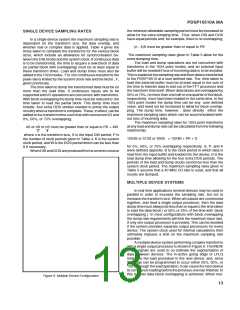
This fast transfer mode is supported by a special option
on the PDSP16540 Bucket Buffer. It will acquire two 1024
point non overlapping blocks using the sampling clock, and
thentransfertheresultstotheFFTprocessoratthefullsystem
clock rate. Figure 8 shows the system arrangement. It does
not support block overlapping.
With1024pointtransformsallblockoverlapsarehandled
bythebufferlogic, andnotbytheinternalRAM, butthedevice
must still be programmed to expect the required overlap if the
external buffer makes use of the in-active LFLG edge to mark
the overlap point. To achieve the performance given in Table
5with50%overlaps, thebuffermustprovidesufficientstorage
for at least 2.5 data blocks. With 75% overlaps it must provide
storage for 2.75 blocks. This extra storage allows transfers
between devices to be only needed when a complete new
block has been acquired for 50% overlaps, and when half a
new block has been acquired for 75% overlaps.If storage is
restrictedtotwodatablocks,onlyhalfthesamplingratesgiven
will be possible. Transfers between devices must then occur
when a half or a quarter of a new block has been acquired.
Since the minimum time between transfers must be no less
than the transform time itself, the sampling rates must be
proportionally reduced to prevent loss of data.
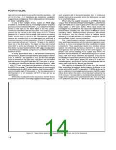
Table 5 Sampliing Rates in MHz Obtained with a Single Device and various overlaps.
12

 MITEL [ MITEL NETWORKS CORPORATION ]