NJ88C50
However the alternation between the N and N+1 values
causes a ripple in the output frequency. This ripple is not
desirable in radio frequency synthesisers. This ripple or jitter
waveform is predictable from the pattern of N and N+1 values
and so can be cancelled.
Typically Ntot(max) might be 10000, with CN(max)=250
and Q=8, so the current step will be of magnitude Ibo/320.
Since Ibo is only 1 uA, this is a very small value; however this
value only applies if Icomp is a continuous current. Icomp
however will be a short current pulse coincident with the Iprop
pulse, in order to cancel jitter components over the widest
possible frequency range.
The instantaneous accumulator value, A, is proportional to
the cumulative frequency error caused by ignoring the
fractional part during the periods of the divide by N. The
accumulator value, A, may therefore be used to generate a
waveform corresponding to the jitter waveform, that is then
used to cancel the jitter out of the phase detector. This jitter
compensation current pulse is equal to A.Icomp where Icomp
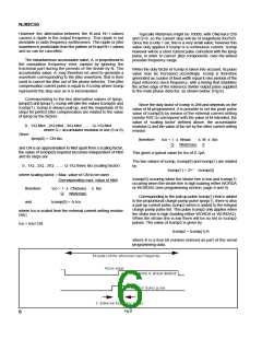
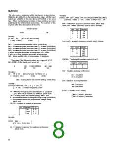
When the duty factor of Icomp is taken into account, its pulse
value may be increased accordingly. Icomp is therefore
generated as a pulse of fixed width equal to two periods of the
input reference clock frequency, with a timing that straddles
the active edge of the reference divider output pulse supplied
to the main phase detector, as shown below: (Fig 6).
represents the step size as A is incremented.
Corresponding to the two alternative values of Iprop,
Iprop(0) and Iprop(1), Icomp will take the values Icomp(0) and
Icomp(1). Icomp is always pull-up, and the magnitude of its
steps for perfect jitter compensation are related to the value
of Iprop by the factors
Since the duty factor of Icomp is 2/M and depends on the
value of M programmed, it is possible to set the peak pulse
value of Icomp(0) by means of the external current setting
resistor RSC to correspond with the value of M intended, the
value of ‘scaling factor’ defined above, the accumulator
modulus Q and the value of Ibo set by the other current setting
resistor.
0 , 1/Q.Ntot , 2/Q.Ntot , 3/Q.Ntot ........ Q-1/Q.Ntot
where Q = accumulator modulus in use (5 or 8)
Since
Iprop(0) = CN.Ibo
therefore
Ico = 1 x Nmax
Ntot(max)
x M x Ibo
Q
2
and CN is an approximation to Ntot apart from a scaling factor,
the value of Icomp(0) required becomes independent of Ntot
and its steps are
This gives a typical value for Ico of 0.1µA.
The two values of Icomp, Icomp(0) and Icomp(1) are related
0 , 1/Q , 2/Q , 3/Q ........ Q-1/Q times Ibo.(scaling factor)
by
Icomp(1) = 2L+1 .Icomp(0)
where scaling factor = Max. value of CN to be used
Icomp(0) occuring when the strobe line is low and Icomp(1)
occuring when the strobe line is high loading either WORDA
or WORDA2 (see programming section, page 8 and 9) .
Corresponding max. value of Ntot
therefore
and
Ico = 1 x CN(max) x Ibo
Ntot(max)
Q
Corresponding to the pull-up pulse Icomp(1) that is added
to the proportional charge pump pulse Iprop(1), there is also
a pull-up current pulse Icomp2 which is added to the integral
charge pump pulse Iint. This pulse Icomp2 only applies when
the stobe line is high (loading either WORDA or WORDA2).
When the strobe line is low there will be no Iint or Icomp2
pulses. The value of Icomp2 is given by
Icomp(0) = A.Ico
where Ico is scaled from the external current setting resistor
RSC.
Ico = Irsc/128.
Icomp2 = Icomp(1).K
where K is a four bit number entered as part of the serial
programming data.
Fig.6
6

 MITEL [ MITEL NETWORKS CORPORATION ]