NJ88C50
The normal value of Iprop, Iprop(0), is obtained while the
strobe line of the serial programming bus is held low. In this
condition, the second charge pump providing the integral
feedback term is inactive.
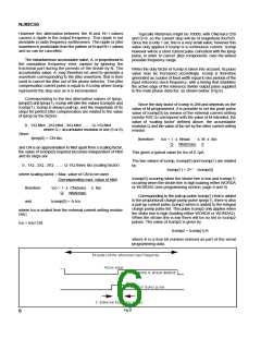
ratio. Using fractional-N the value of N is alternated between
N and N+1 in order to simulate a fractional part. For example
9000.375 would be simulated by alternating between 9000
and 9001 in the pattern
9000, 9000, 9001, 9000, 9000, 9001, 9000, 9001 (mean value of 9000.375).
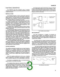
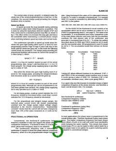
Speed up Mode
In speed up mode the loop bandwith during switching
is increased to allow faster initial frequency acquisition. This
is done by using the dual phase detector outputs (PDP and
PDI) connected to a standard passive loop filter as shown in
fig.5. The effect of this is to increase the loop gain and hence
the bandwidth while maintaining a constant phase margin
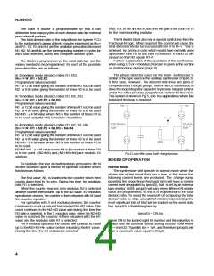
On the NJ88C50 the fractional-N circuit consists of an
accumulator which can be set to overflow at a value of 5 or 8
(FMOD in programming word D, see page 9). The value in the
accumulator, A, is incremented once every comparison cycle
of the main phase detector and every time the accumulator
overflows the total division ratio of the synthesiser and
prescaler is increased from N to N+1. To obtain the pattern
described above N=9000 and FMOD would be set to mod8
and the incremental value, NF(programmed in word A) would
be set to 3. The accumulator would then behave as shown
below.
when switching between speed up mode and normal mode.
The synthesiser operates in speed up mode when the
strobe line goes high loading either word A or word A2 (see
programming section Page 8-Page 9) and it will stay in this
mode until the strobe line goes low. In this mode the following
current levels are produced. The charge pump providing the
proportional feedback will increase its current from Iprop(0) to
a value Iprop(1), where
Increment
Accumulator Total Division
Value
Value
Ratio
9000
9000
9001
9000
9000
9001
9000
9001
3
3
3
3
3
3
3
3
3
6
1
4
7
2
5
0
Iprop(1) = 2L+1 .Iprop(0)
where L is a two bit number loaded as part of the serial
programming data. Iprop(1) will therefore be 2, 4, 8 or 16
times Iprop(0). The charge pump supplying Iprop is specified
up to a value of 1mA.
Also when the strobe line goes high loading word A or
word A2, the charge pump providing the integral feedback
term becomes active at a current level Iint given by
Varying NF allows different fractions to be obtained. If NF=1
and FMOD=8 the accumulator would overflow once in every
8 cycles giving a value of 9000.125. Similarly if NF=4 the
accumulator overflows every other cycle giving 9000.5.
Iint = K.Iprop(1)
For a given step size this increase in resolution means a higher
comparison frequency at the phase detector, and therefore a
lower overall division ratio. For example,
where K is a four bit number loaded as part of the serial
programming data. Although Iint can be programmed to be
240 times greater than Iprop(0), the charge pump supplying
Iint is only specified up to a value of 10mA.
with a
step size = 200kHz
and carrier frequency = 900MHz
For all charge pumps, a pull-up current indicates the VCO
frequency should be increased while a pull-down current
indicates the VCO frequency should be decreased.
Non fractional-N synthesiser
Comparison frequency=200kHz
Division ratio=900MHz=4500
For the proportional and integral charge pumps, the
selected pulse current levels will remain substantially
constant over the charge pumps output voltage ranges
tabulated in the electric characteristics. “Substantially
constant” means that the current will not have changed by
more than 10% of the value measured at 2.5 volts on the
output .
200kHz
Fractional-N synthesiser (using 5ths)
Comparison frequency=1MHz
Division ratio=900MHz=900
1MHz
In most applications the phase noise is proportional to the
overall division ratio. Therefore fractional-N gives lower phase
noise. This higher comparison frequency and lower phase
noise allows circuits to be built with wider loop bandwidths
while keeping the same stability. This means that phase
locked loops (PLLs) can be made to either switch faster for a
given phase noise or be quieter for a given switching speed,
compared to conventional designs.
FRACTIONAL-N OPERATION
Conventional, non fractional-N synthesisers have a
frequency resolution or step size equal to the phase detector
comparison frequency. Fractional-N refers to a technique
which allows finer frequency steps to be obtained.
The synthesised frequency with a conventional
synthesiser is equal to N times the phase detector comparison
frequency, where N is the programmable integer loop divide
5

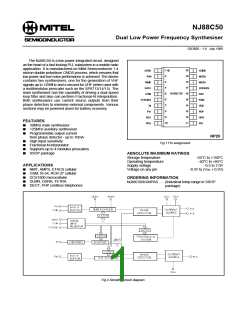
 MITEL [ MITEL NETWORKS CORPORATION ]