NJ88C50
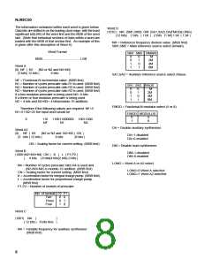
If a 64/65/72 prescaler is used all the channels will now be
selectable as the minimum required division ratio will now be
greater than the minimum allowable division ratio (1096).
MULTIMODULUS DIVISION
The NJ88C50 supports the use of 2, 3 and 4 modulus
prescalers. Two modulus prescalers such as the SP8714/15
are commonly used in PLLs. Additional information on using
2 modulus prescalers can be found in application note AN132
in the GEC Plessey Semiconductors Personal
Communications handbook (May 1992).
SERIAL DATA BUS
The data needed to program the synthesiser is entered via
a high speed (10MBit/s) 3-wire bus, with serial data, serial
clock and strobe pins. The input data is partitioned so that
after initial programming the output frequency can be
changed by re-programming only 24 or 32 bits.The timing
diagram for the bus is given in Fig.7.
When using a 2 modulus prescaler (R/R+1) the minimum
division ratio above which all channels can be synthesised is
given by
Minimum division ratio = R(R-1)
The data is programmed as either four twenty-four bit
words or three twenty-four bit words and one thirty-two bit
word. When initially programmed words A, B, C and D are
loaded, though if the auxiliary synthesiser is disabled C is not
needed. Following the initial programming the frequency can
be subsequently shifted in one of the following ways:
a) If a 2 or 3 ratio prescaler is being used and CN does
not need to be reprogrammed word A should be
loaded.
eg. for a 64/65 prescaler such as the SP8714/15
Minimum division ratio = 64(64-1) = 4032
When fractional-N operation is being used higher comparison
frequencies are used, which are obtained by using lower
division ratios. Use of a 3 or 4 modulus prescaler allows the
minimum division ratio to be lowered.
b
If a 2 or 3 ratio prescaler is being used and CN does
need to be reprogrammed word A2 should be loaded.
In wide frequency band systems CN must be
reprogrammed for best performance every time the
frequency is changed.
For a 3 modulus prescaler (R/R+1/R+A)
Minimum division ratio = R(R+A+1)+A
c) If a four ratio prescaler is being used word A and word
B should be loaded
A
eg. for a 64/65/72 prescaler such as the SP8713
Minimum division ratio = 64(64+8+1)+8 = 1096
8
For a 4 modulus prescaler (R/R+1/R+A/R+B)
Minimum division ratio = R(A+B+R+1)+A+B
A B
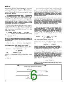
Data must be valid on positive edges of clock
Fig.7
eg. for a 64/65/68/80 prescaler
Minimum division ratio = 64(4+16+64+1)+4+16 = 852
A strobe pulse occurs at the end of each word and loads
the contents of the input shift register into the working
registers, except when word B is being loaded, in which case
the shift register contents are loaded into a temporary register
and then loaded into the working register when either word A
or A2 is loaded. The information is transferred on the rising
edge of the strobe pulse which should occur one half clock
period after the clock edge on which the MSB of a word is
shifted in.
4 16
An example of where three modulus division would be
implemented is given below.
The system in which the synthesiser is to operate has a lowest
carrier frequency of 900MHz and a channel spacing of 30kHz.
However due to the lock up time requirements fractional-N
operation is being used in its 8ths mode (see section on
fractional-N operation), giving a comparison frequency of
30kHz x 8 = 240kHz.
If word A or word A2 is being loaded, when the strobe goes
high the main synthesiser will be put into speed-up mode. This
mode will be maintained while the strobe remains high. During
this time any pulses on the clock input will not affect the
function of the synthesiser.
Therefore,
Minimum division ratio required = 900x106 = 3750
240x103
If a 64/65 prescaler is used not all the channels will be
selectable as the minimum required division ratio is less than
the minimum allowable division ratio (4032).
7

 MITEL [ MITEL NETWORKS CORPORATION ]