Advance Information
MT9160B/61B
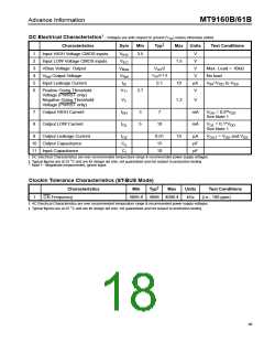
DC Electrical Characteristics† - Voltages are with respect to ground (V ) unless otherwise stated.
SS
‡
Characteristics
Sym
Min
Typ
Max Units
Test Conditions
1
2
3
4
5
6
Input HIGH Voltage CMOS inputs
Input LOW Voltage CMOS inputs
VBias Voltage Output
V
3.5
V
IHC
V
1.5
V
V
ILC
V
VDD/2
Max. Load = 10kΩ
Bias
V
/2-1.9
V
Output Voltage
V
V
No load
DD
Ref
Ref
Input Leakage Current
I
0.1
10
µA
V
V =V to V
IZ
IN
DD
SS
Positive Going Threshold
Voltage (PWRST only)
Negative Going Threshold
Voltage (PWRST only)
V
3.7
T+
V
1.3
V
T-
7
8
9
Output HIGH Current
Output LOW Current
Output Leakage Current
I
3
5
7
mA
mA
V
= 0.9*V
DD
OH
OH
See Note 1
V = 0.1*V
OL
See Note 1
V = V and V
OUT
I
10
OL
DD
I
0.01
15
10
µA
pF
pF
OZ
DD
SS
10 Output Capacitance
11 Input Capacitance
C
o
C
10
i
† DC Electrical Characteristics are over recommended temperature range & recommended power supply voltages.
‡ Typical figures are at 25 °C and are for design aid only: not guaranteed and not subject to production testing.
* Note 1 - Magnitude measurement, ignore signs.
Clockin Tolerance Characteristics (ST-BUS Mode)
‡
Characteristics
C4i Frequency
Min
Typ
Max
Units
Test Conditions
1
4095.6 4096 4096.4
kHz
(i.e., 100 ppm)
† AC Electrical Characteristics are over recommended temperature range & recommended power supply voltages.
‡ Typical figures are at 25 °C and are for design aid only: not guaranteed and not subject to production testing.
96

 MITEL [ MITEL NETWORKS CORPORATION ]