MT9079
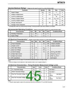
AC Electrical Characteristics- Microprocessor Timing
Characteristics
Sym Min
Typ
Max
Units
Conditions/Notes
1
2
3
4
5
6
7
8
9
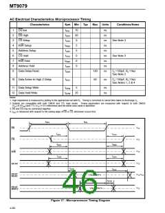
DS low
tDSL
tDSH
tCSS
tRWS
tADS
tCSH
tRWH
tADH
tDDR
70
50
0
ns
ns
ns
ns
ns
ns
ns
ns
ns
DS High
CS Setup
See Note 3
R/W Setup
5
Address Setup
CS Hold
5
0
See Note 3
R/W Hold
0
Address Hold
Data Delay Read
0
120
50
CL=150pF, RL=1kΩ
See Note 2
10 Data Active to High Z Delay
tDAZ
ns
CL=150pF, RL=1kΩ
See Notes 1, 2 & 4
11 Data Setup Write
12 Data Hold Write
tDSW
tDHW
5
ns
ns
25
Notes:
1. High impedance is measured by pulling to the appropriate rail with RL. Timing is corrected to cancel time taken to discharge CL.
2. Outputs are compatible with both CMOS and TTL logic levels. Timing parameters are measured with respect to both CMOS
(VCT=0.5VDD) and TTL (VTT=1.5V) references and the worst case value is specified.
3. DS and CS may be connected together.
4. tDAZ is measured with respect to the raising edge of DS or CS, whichever occurs first.
tDSL
tDSH
VTT
VTT
VTT
DS
CS
tCSS
tCSH
tRWH
tRWS
R/W
tADS
tADH
VTT
A0-A4
tDDR
tDAZ
D0-D7
READ
VTT,VCT
VALID DATA
tDSW
tDHW
D0-D7
WRITE
VTT
VALID DATA
Figure 17 - Microprocessor Timing Diagram
4-282

 MITEL [ MITEL NETWORKS CORPORATION ]