Preliminary Information
MT9076
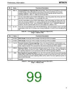
Bit
Name
Functional Description
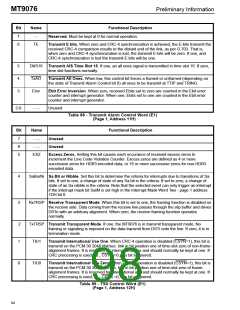
7-4
TMA1-4 Transmit Multiframe Alignment Bits One to Four. These bits are transmitted on the PCM
30 2048 kbit/sec. link in bit positions one to four of time slot 16 of frame zero of every
signaling multiframe. These bits are used by the far end to identify specific frames of a
signaling multiframe. TMA1-4 = 0000 for normal operation.
3
2
X1
This bit is transmitted on the PCM 30 2048 kbit/sec. link in bit position five of time slot 16 of
frame zero of every multiframe. X1 is normally set to one.
Y
This bit is transmitted on the PCM 30 2048 kbit/sec. link in bit position six of time slot 16 of
frame zero of every multiframe. It is used to indicate the loss of multiframe alignment to the
remote end of the link. If one - loss of multiframe alignment; if zero - multiframe alignment
acquired. This bit is ignored when AUTY is zero (page 01H, address 11H).
1, 0
X2, X3 These bits are transmitted on the PCM 30 2048 kbit/sec. link in bit positions seven and eight
respectively, of time slot 16 of frame zero of every multiframe. X2 and X3 are normally set to
one.
Table 90 - Transmit Multiframe Alignment Signal (E1)
(Page 1, Address 13H)
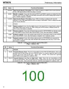
Bit
Name
Functional Description
7
6
5
DSToEn DSTo Enable. If zero pin DSTo is tristate. If set the pin DSTo is enabled.
CSToEn CSTo Enable. If zero pin CSTo is tristate. If set the pin CSTo is enabled.
TxCCS Transmit Common Channel signaling. If one, the transmit channel 16 of the device is in
common channel signaling (CCS) mode. If zero, it is in Channel Associated signaling (CAS)
mode, data for channel 16 is sourced from the internal transmission ABCD register.
4
3
DBNCE Debounce Select. This bit selects the debounce period (1 for 14 msec.; 0 for no debounce).
Note: there may be as much as 2 msec. added to this duration because the state change of
the signaling equipment is not synchronous with the PCM 30 signaling multiframe.
MSN
Most Significant signaling Nibble. If one, the CSTo and CSTi channel associated signaling
nibbles will be valid in the most significant portion of each ST-BUS time slot. If zero, the CSTo
and CSTi channel associated signaling nibbles will be valid in the least significant portion of
each ST-BUS time slot.
2,1,0
- - -
Unused.
Table 91 - Interrupt and signaling Control Word (E1)
(Page 1, Address 14H)
95

 MITEL [ MITEL NETWORKS CORPORATION ]