MT9076
Preliminary Information
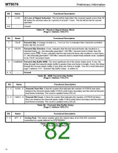
Bit
Name
Functional Description
7
LLOS
LIU Loss of Signal indication. This bit will be high when the received signal is less than 40
dB below the nominal value for a period of at least 1 msec. This bit will be low for normal
operation.
6-0
- - -
Unused
Table 57 - Receive Signal Status Word
(Page 3, Address 16H) (T1)
Bit
Name
Functional Description
7
TSLIP
Transmit Slip. A change of state (i.e., 1-to-0 or 0-to-1) indicates that a transmit controlled
frame slip has occurred.
6
TSLPD Transmit Slip Direction. If one, indicates that the last transmit frame slip resulted in a
repeated frame, i.e., the internally generated 1.544 Mhz. transmit clock is faster than the
system clock (C4b). If zero, indicates that the last transmit frame slip resulted in a lost frame,
i.e., the internally generated 1.544 Mhz. transmit clock is slower than network clock. Updated
on an TSLIP occurance basis.
5
TxSBMSB Transmit Slip Buffer MSB. The most significant bit of the phase status word. If one, the
delay through the transmit elastic buffer is greater than one frame in length; if zero, the delay
through the receive elastic buffer is less than one frame in length. This bit is reset whenever
page 3 address 17H - Transmit Slip Buffer Delay - is written to.
4 - 0
- - -
Unused.
Table 58 - MSB Transmit Slip Buffer
(Page 3, Address 17H) (T1)
Bit
Name
Functional Description
7 - 3
TxTS4 - 0 Transmit Time Slot. A five bit counter that indicates the number of STBUS time slots
between the transmit elastic buffer STBUS write frame boundary and the internal transmit
read frame boundary. The count is updated every 250 uS.
2 - 0
TxBC2 - 0 Transmit Bit Count. A three bit counter that indicates the number of STBUS bit times
there are between the transmit elastic buffer STBUS write frame boundary and the internal
read frame boundary. The count is updated every 250 uS.
Table 59 - Transmit Slip Buffer Delay
(Page 3, Address 18H) (T1)
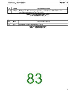
Bit
Name
Functional Description
7 - 0
AP7 - 0
Analog Peak. This status register gives the output value of an 8 bit A/D converter
connected to a peak detector on RTIP/RRING.
Table 60 - Analog Peak Detect
(Page 3, Address 1DH) (T1)
78

 MITEL [ MITEL NETWORKS CORPORATION ]