Preliminary Information
MT9076
3.3.2
CRC-4 Multiframing in E1 mode
The primary purpose for CRC-4 multiframing is to provide a verification of the current basic frame alignment,
although it can also be used for other functions such as bit error rate estimation. The CRC-4 multiframe
consists of 16 basic frames numbered 0 to 15, and has a repetition rate of 16 frames X 125 microseconds/
frame = 2 msec.
CRC-4 multiframe alignment is based on the 001011 bit sequence, which appears in bit position one of the first
six NFASs of a CRC-4 multiframe.
The CRC-4 multiframe is divided into two submultiframes, numbered 1 and 2, which are each eight basic
frames or 2048 bits in length.
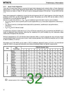
The CRC-4 frame alignment verification functions as follows. Initially, the CRC-4 operation must be activated
and CRC-4 multiframe alignment must be achieved at both ends of the link. At the local end of a link, all the bits
4
4
of every transmit submultiframe are passed through a CRC-4 polynomial (multiplied by X then divided by X +
X + 1), which generates a four bit remainder. This remainder is inserted in bit position one of the four FASs of
the following submultiframe before it is transmitted (see Table 12).
The submultiframe is then transmitted and, at the far end, the same process occurs. That is, a CRC-4
remainder is generated for each received submultiframe. These bits are compared with the bits received in
position one of the four FASs of the next received submultiframe. This process takes place in both directions of
transmission.
When more than 914 CRC-4 errors (out of a possible 1000) are counted in a one second interval, the framing
algorithm will force a search for a new basic frame alignment. See Frame Algorithm section for more details.
The result of the comparison of the received CRC-4 remainder with the locally generated remainder will be
transported to the far end by the E-bits. Therefore, if E = 0, a CRC-4 error was discovered in a submultiframe
1
1 received at the far end; and if E = 0, a CRC-4 error was discovered in a submultiframe 2 received at the far
2
end. No submultiframe sequence numbers or re-transmission capabilities are supported with layer 1 PCM 30
protocol. See ITU-T G.704 and G.706 for more details on the operation of CRC-4 and E-bits.
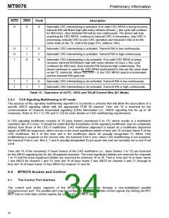
There are two CRC multiframe alignment algorithm options selected by the AUTC control bit (address 10H,
page 01H). When AUTC is zero, automatic CRC-to-non-CRC interworking is selected. When AUTC is one and
ARAI is low, if CRC-4 multiframe alignment is not found in 400 msec, the transmit RAI will be continuously high
until CRC-4 multiframe alignment is achieved.
The control bit for transmit E bits (TE, address 11H of page 01H) will have the same function in both states of
AUTC. That is, when CRC-4 synchronization is not achieved the state of the transmit E-bits will be the same as
the state of the TE control bit. When CRC-4 synchronization is achieved the transmit E-bits will function as per
ITU-T G.704. Table 12 outlines the operation of the AUTC, ARAI and TALM control bits of the MT9076.
29

 MITEL [ MITEL NETWORKS CORPORATION ]