Preliminary Information
MT9075A
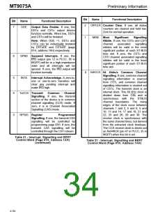
Bit
Name
Functional Description
Bit
Name
Functional Description
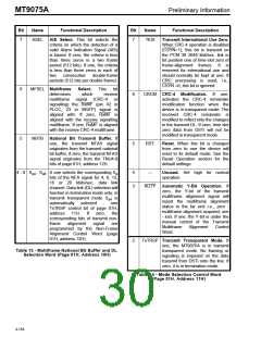
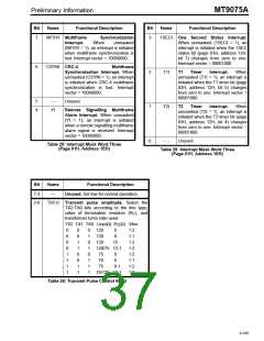
7
TAIS
Transmit Alarm Indication Signal.
If one, an all ones signal is
transmitted. TAIS=0 for normal
operation.
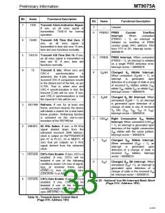
7
6
---
Unused.
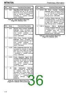
PRBSO PRBS
Interrupt.
(PRBSO
Counter
Overflow
unmasked
When
=
1), an interrupt is
6
5
4
TAIS0 Transmit AIS Time Slot Zero. If
one, an all ones signal is
transmitted in time slot zero. If zero,
time slot zero functions normally.
initiated on overflow of PRBS
counter (page 04H, address 10H)
from FFH to 0H. Interrupt vector =
00000010.
TAIS16 Transmit AIS Time Slot 16. If one,
an all ones signal is transmitted in
time slot 16. If zero, time slot
functions normally.
5
4
PRBSI PRBS Interrupt. When unmasked
(PRBSI = 1), an interrupt is initiated
on a single PRBS detection error.
Interrupt vector = 00000010.
TE
Transmit E bits. When zero and
CRC-4 synchronization is
S nibI Changed
S
Nibble Interrupt.
a
a
When unmasked (S nibI = 1), an
a
achieved, the E-bits transmit the
received CRC-4 comparison results
to the distant end of the link, as per
G.704. That is, when zero and
CRC-4 synchronization is lost, the
transmit E-bits will be zero. If one,
and CRC-4 synchronization is lost
the transmit E-bits will be one.
interrupt
detection of a change of state in any
of received S nibbles (nibble S ,
is
generated
upon
a
a5
nibble S , nibble S or nibble S ).
a6
a7
a8
Interrupt vector = 00000010.
3
2
1
0
S bitI Changed S Bit Interrupt. When
a
a
unmasked (S bitI = 1), an interrupt
is generated upon detection of a
change of state in any of received
a
3
2
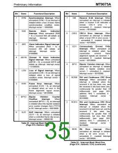
REFRM Reframe. If one for at least one
frame, and then cleared, the device
will initiate a search for a new basic
frame position. Reframing function
is activated on the one-to-zero
transition of the REFRM bit.
S
bits (S , S , S
or S ).
a
a5
a6
a7 a8
Interrupt vector = 00000010.
C8S I Eight Consecutive S
Nibble
a6
a6
Interrupt. When unmasked (C8S I
= 1), an interrupt is generated upon
detection of the eighth consecutive
a6
64KSEL 64 KHz Select. If one, a 64 KHz
signal divided down from the
extracted received 2048 kbit/sec.
clock is output on RxFP/Rx64KCK
(pin 47 in PLCC, 35 in MQFP). If
zero that pin outputs an 8 KHz
signal derived from the extracted
clock.
S
nibble with the same pattern.
a6
Interrupt vector = 00000010.
S I
Changed S Nibble Interrupt.
When unmasked (S I = 1), an
interrupt
detection of a change of state in
received nibbles. Interrupt
vector = 00000010.
a6
a6
a6
is
generated
upon
S
a6
1
0
DSToDE DSTo Data Enable. If zero, DSTo is
enabled. If one, DSTo will be
tristated if one of the following
conditions exists: LIU loss of signal,
loss of terminal frame sync
(SYNC=1), loss of CRC4 sync
(CRCSYN=1) or AIS.
S I
Changed S Bit Interrupt. When
a5
unmasked (S I =1), an interrupt is
generated upon detection of a
change of state in the received S
bit. Interrupt vector = 00000010.
a5
a5
a5
CSToDE CSTo Data Enable. If zero, CSTo is
enabled. If one, CSTo will be
tristated if one of the following
conditions exists: loss of multiframe
sync (MFSYNC=1), or AIS16 =1
Table 20 - National Use Bit Interrupt Mask Word
(Page 01H, Address 19H)
Table 19 - Transmit Alarm Control Word
(Page 01H, Address 16H)
4-161

 MITEL [ MITEL NETWORKS CORPORATION ]