MT9075A
Preliminary Information
The end-of-packet-detect (EOPD) interrupt indicates
that the last byte written to the RX FIFO was an EOP
byte. The end-of-packet-read (EOPR) interrupt
indicates that the byte about to be read from the RX
FIFO is an EOP byte. The Status Register should be
read to see if the packet is good or bad before the
byte is read.
Slip Buffer
In addition to the elastic buffer in the jitter
attenuator(JA), another elastic buffer (two frames
deep) is present, attached between the receive side
and the ST-BUS (or GCI Bus) side of the MT9075A.
This elastic buffer is configured as a slip buffer which
absorbs wander and low frequency jitter in multi-
trunk applications. The received PCM 30 data is
clocked into the slip buffer with the E2o clock and is
clocked out of the slip buffer with the C4b clock. The
E2o extracted clock is generated from, and is
therefore phase-locked with, the receive PCM 30
data. In normal operation, the E2o clock will be
phase-locked to the C4b clock by an external phase
locked loop (PLL). Therefore, in a single trunk
system the receive data is in phase with the E2o
clock, the C4b clock is phase-locked to the E2o
clock, and the read and write positions of the slip
buffer will remain fixed with respect to each other.
A minimum size packet has an 8-bit address, an 8-bit
control byte, and a 16-bit FCS pattern between the
opening and closing flags. Thus, the absence of a
data transmission error and a frame length of at least
32 bits results in the receiver writing a valid packet
code with the EOP byte into RX FIFO. The last 16
bits before the closing flag are regarded as the FCS
pattern and will not be transferred to the receiver
FIFO. Only data bytes (Address, Control,
Information) are loaded into the Rx FIFO.
In the case of an RX FIFO overflow, no clocking
occurs until a new opening flag is received. In other
words, the remainder of the packet is not clocked into
the FIFO. Also, the top byte of the FIFO will not be
written over. If the FIFO is read before the reception
of the next packet then reception of that packet will
occur. If two beginning of packet conditions (RQ9=0;
RQ8=1) are seen in the FIFO, without an
intermediate EOP status, then overflow occurred for
the first packet.
In a multi-trunk slave or loop-timed system (i.e.,
PABX application) a single trunk will be chosen as a
network synchronizer, which will function as
described in the previous paragraph. The remaining
trunks will use the system timing derived from the
synchronizer to clock data out of their slip buffers.
Even though the PCM 30 signals from the network
are synchronous to each other, due to multiplexing,
transmission impairments and route diversity, these
signals may jitter or wander with respect to the
synchronizing trunk signal. Therefore, the E2o clocks
of non-synchronizer trunks may wander with respect
to the E2o clock of the synchronizer and the system
bus.
The receiver may be enabled independently of the
transmitter. This is done by setting the RxEN bit of
Control Register 1. Enabling happens immediately
upon writing to the register. Disabling using RxEN
will occur after the present packet has been
completely loaded into the FIFO. Disabling can occur
during a packet if no bytes have been written to the
FIFO yet. Disabling will consist of disabling the
internal receive clock. The FIFO, Status, and
Interrupt Registers may still be read while the
receiver is disabled. Note that the receiver requires a
flag before processing a frame, thus if the receiver is
enabled in the middle of an incoming packet it will
ignore that packet and wait for the next complete
one.
Network standards state that, within limits, trunk
interfaces must be able to receive error-free data in
the presence of jitter and wander (refer to network
requirements for jitter and wander tolerance). The
MT9075A will allow a maximum of 26 channels (208
UI, unit intervals) of wander and low frequency jitter
before a frame slip will occur.
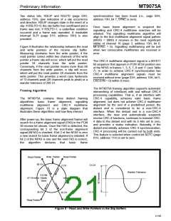
The minimum delay through the receive slip buffer is
approximately two channels and the maximum delay
is approximately 60 channels (see Figure 9).
The receive CRC (FCS) can be monitored in the Rx
CRC Registers (address 18H and 19H). These
registers contain the actual CRC sent by the other
transmitter in its original form, that is, MSB first and
bits inverted. These registers are updated by each
end of packet (closing flag) received and therefore
should be read when an end of packet is received so
that the next packet does not overwrite the registers.
When the C4b and the E2o clocks are not phase-
locked, the rate at which data is being written into the
slip buffer from the PCM 30 side may differ from the
rate at which it is being read out onto the ST-BUS. If
this situation persists, the delay limits stated in the
previous paragraph will be violated and the slip
buffer will perform a controlled frame slip. That is, the
buffer pointers will be automatically adjusted so that
a full PCM 30 frame is either repeated or lost. All
frame slips occur on PCM 30 frame boundaries.
4-148

 MITEL [ MITEL NETWORKS CORPORATION ]