Preliminary Information
MT9075A
the tag bits being loaded in the FIFO, Control
Register 1 must be written to before writing to the
FIFO. However, EOP and FA are reset after writing to
the TX FIFO. The Transmit Byte Count Register may
also be used to tag an EOP. The register is loaded
with the number of bytes in the packet and
decrements after every write to the Tx FIFO. When a
count of one is reached, the next byte written to the
FIFO is tagged as an end of packet. The register
may be made to cycle through the same count if the
packets are of the same length by setting Control
Register 2, bit Cycle (at address 15H of page 0BH
for HDLC0 or 0CH for HDLC1).
cleared. Disabling will consist of stopping the
transmitter clock. The Status and Interrupt Registers
may still be read, and the FIFO and Control
Registers may be written to while the transmitter is
disabled. The transmitted FCS may be inhibited
using the Tcrci bit of Control Register 2. In this mode
the opening flag followed by the data and closing flag
is sent and zero insertion is still included, but no
FCS. That is, the FCS is injected by the
microprocessor as part of the data field. This is used
in V.120 terminal adaptation for synchronous
protocol sensitive UI frames.
HDLC Receiver
If the transmitter is in the Idle Channel state when
data is written to the TX FIFO, then an opening flag
is sent and data from TX FIFO follows. Otherwise,
data bytes are transmitted as soon as the current
flag byte has been sent. TX FIFO data bytes are
continuously transmitted until either the FIFO is
empty or an EOP or FA status bit is read by the
transmitter. After the last bit of the EOP byte has
been transmitted, a 16-bit FCS is sent followed by a
closing flag. When multiple packets of data are
loaded into TX FIFO, only one flag is sent between
packets.
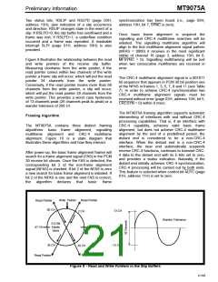
After initialization and enabling, the receiver clocks in
serial data, continuously checking for Go-Aheads (0
1111 1110), flags (0111 1110), and Idle Channel
states (at least fifteen ones). When a flag is
detected, the receiver synchronizes itself to the
serial stream of data bits, automatically calculating
the FCS. If the data length between flags after zero
removal is less than 25 bits, then the packet is
ignored so no bytes are loaded into Rx FIFO. When
the data length after zero removal is between 25 and
31 bits, a first byte and bad FCS code are loaded
into the Rx FIFO. For an error-free packet, the result
in the CRC register should match the HEX pattern of
“F0B8” when a closing flag is detected.
Frame Aborts (FA, the transmission of 7F hex), are
transmitted by tagging a byte previously written to
the TX FIFO. When a byte has an FA tag, then an FA
is sent instead of that tagged byte. That is, all bytes
previous to but not including that byte are sent. After
an FA, the transmitter returns to the Mark Idle or
Interframe Time Fill state, depending on the state of
the Mark idle control bit.
If address recognition is required, the Receiver
Address Recognition Registers (address 10H and
11H) are loaded with the desired address and the
Adrec bit in the Control Register 1 (address 13H) is
set to one. Bit 0 of the Address Registers is used as
an enable bit for that byte, thus allowing either or
both of the first two bytes to be compared to the
expected values. In addition, seven bits of address
comparison can be realized on the first byte if this is
a single byte address by setting the Seven bit of
Control Register 2 (address 15H).
TX FIFO underrun will occur if the FIFO empties and
the last byte did not have either an EOP or FA tag. A
frame abort sequence will be sent when an underrun
occurs.
Below is an example of the transmission of a three
byte packet (’AA’’03’’77’ hex) (Interframe time fill).
TxEN can be enabled before or after this sequence.
Two Status Register bits (RQ8 and RQ9) are
appended to each data byte as it is written to the Rx
FIFO. They indicate that a good packet has been
received (good FCS and no frame abort), or a bad
packet with either incorrect FCS or frame abort. The
Status and Interrupt Registers should be read before
reading the Rx FIFO since status and interrupt
information correspond to the byte at the output of
the FIFO (i.e., the byte about to be read). The Status
Register bits are encoded as follows:
(a) Write’04’ to Control Register 1 - Mark Idle bit set
(b) Write’AA’ to Tx FIFO -Data byte
(c) Write’03’ to Tx FIFO - Data byte
(d) Write’34’ to Control Register 1 - TxEN; EOP;
Mark Idle bits set
(e) Write’77’ to Tx FIFO - Final data byte
RQ9
RQ8
Byte status
last byte (bad packet)
bad packet
The transmitter may be enabled independently of the
receiver. This is done by setting the TxEN bit of the
Control Register. Enabling happens immediately
upon writing to the register. Disabling using TxEN
will occur after the completion of the transmission of
the present packet; the contents of the FIFO are not
1
0
1
0
1
1
0
0
last byte (good packet)
packet byte
4-147

 MITEL [ MITEL NETWORKS CORPORATION ]