MT8931C
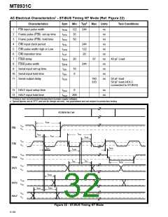
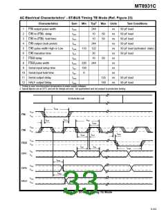
AC Electrical Characteristics† - ST-BUS Timing TE Mode (Ref. Figure 23)
‡
Characteristics
Sym
Min
Typ
Max
Units
Test Conditions
50 pF load
1
2
3
4
5
6
7
8
9
F0b output pulse width
C4b to (F0b) delay
C4b to (F0b) hold time
C4b output clock period
C4b pulse width High or Low
C4b transition time
tFPW
tCFD
tCFH
tP4o
244
10
ns
ns
ns
ns
ns
ns
ns
ns
ns
ns
ns
ns
50
50
50 pF load
50 pF load
50 pF load
10
244
122
20
tC4W
tC4T
tDFD
tDFW
tSIS
110
50 pF load (activated state)
50 pF load
F0od delay
10
50
F0od pulse width
220
150
0
244
Serial input setup time
10 Serial input hold time
11 Serial output delay
12 HALF output Delay
tSIH
tSOD
125
150
50 pF load
50 pF load
tHAD
† Timing is over recommended temperature & power supply voltages
‡ Typical figures are at 25°C and are for design aid only: not guaranteed and not subject to production testing.
ST-BUS Bit Cell
tFPW
VOH
F0b
VOL
tCFH
tP4o
tCFD
tC4W
VOH
VOL
C4b
tDFD
tC4T
tC4W
VOH
VOL
F0od
DSTi
tSIS
tSIH
tDFW
VIH
VIL
tSOD
VOH
VOL
DSTo
HALF
tHAD
VOH
VOL
Figure 23 - ST-BUS Timing TE Mode
9-103

 MITEL [ MITEL NETWORKS CORPORATION ]