MT8924
Preliminary Information
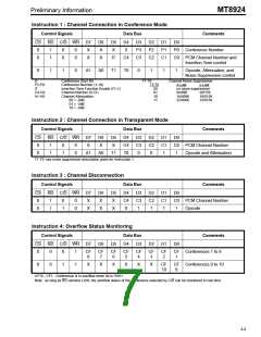
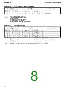
Instruction 5 : PCM Operating Mode Selection
Control Signals
Data Bus
Comments
CS
0
RD C/D WR D7
D6
E
D5
F1
D4
F0
D3
0
D2
1
D1
0
D0
1
1
1
0
X
see Table 1
E:
Extra bit insertion (active when E=1)
F1 - F0:
PCM byte format selection (see Table 1)
00 = no bit inverted
01 = even bit (B0, B2, B4, B6) inverted
10 = odd bit (B1, B3, B5) inverted
11 = all bits (B0, B1, B2, B3, B4, B5, B6) inverted
Instruction 6 : Status Monitoring
Control Signals
Data Bus
Comments
CS
0
RD C/D WR D7
D6
X
D5
X
D4
C4
X
D3
C3
0
D2
C2
1
D1
C1
1
D0
C0
0
1
1
0
0
1
1
0
0
1
X
X
0
X
X
0
P3
P2
P1
P0
A1
A0
T1
T0
P3 - P0:
channel mode operation information
0000 = no connection
A1 - A0:
see channel attenuation description
for Instruction 1
1111 = transparent mode
1010 - 0001 = conference mode
P3 - P0 provides conference number
T1 - T0:
see noise suppression description
for Instruction 1
Note:
Instruction 6 enables the data bus to read the status until reset by C/D=0, WR=1, and CS=0
8-10

 MITEL [ MITEL NETWORKS CORPORATION ]